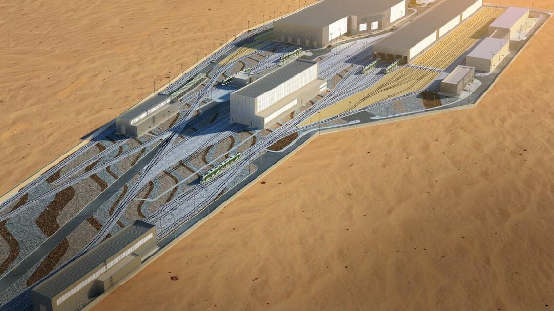
Eversendai Engineering Saudi LLC, was awarded the Pacakage-1 of Riyadh Metro Depots Project comprises 10,000 M Tons steelworks on Line-1 South & North Depots as well as Line-2 East Depots.
The scope of Eversendai was to provide Connection Design, Shop Drawings, BIM Implementation & Coordination, Erection Engineering Study & Stage Analysis, Workshop Fabrication Drawings, Supply, Fabrication, Painting, Fire Proofing, Composite Floor Decking, and Erection of Structural Steel Works. The Roofing and Cladding works were also awarded to Eversendai.
All the above scope of works was completely taken care in-house and successfully being completed in line with project schedules.
The Project Client is Arriyadh Development Authority (ADA), The Main Contractor is BACS, The Architect & Structural Engineer is Bechtel.
Riyadh Metro Network will provide 6 Mainlines in the city Riyadh to form the backbone of the future Riyadh Public Transport Network. The six-line metro system that will run for a total length of 176 kilometers across the city and includes 85 stations. The Project is divided into 3 Packages. The Package-1 comprises of the Lines-1 & 2. The Line-1 is a North-South Line along Olaya – King Faisal – Batha Corridor. The Line-2 is a East-West line along King Abdullah Road.
The Riyadh Metro Depots in Line -1 & Line-2 consists of Workshops, Stabling & Manual Wash, Paint Bldgs, Vehicle Wash, Light Maintenance & Permanent way buildings
The Building dimensions of each structure are:
LINE 1 SOUTH: Workshop building structure (164m x 77m), Stabling & Manual wash Structure (260m x 40m),Light Maintenance Structure (93m x 40m), Paint Building Structure (51m x 15m),Permanent Way Building Structure (97m x 20m), Vehicle wash building structure (60m x 13m),
LINE 1 NORTH: Stabling building preliminary structure (268m x 32m), Workshop preliminary structure (104m x 54m)
LINE 2 EAST: Workshop building structure (244m x 73m), Stabling & Manual wash Structure (274m x 32m),Paint Building Structure (51m x 15m),Permanent Way Building Structure (97m x 20m), Vehicle wash building structure (60m x 13m).
WORKSHOP BUILDINGS: The whole structure is a combination of steel super structure and concrete sub structure. The building consists of central workshop area, either side Admin blocks of G+ 2 and Light maintenance block attached to workshop. The workshop covered with portal frames having span of 24 m (max), eave height is 12 m and bay spacing of 9 m. The super structure consists of the steel columns, Trusses, Rafters, beams, purlins, Girts, walls and roofs. The whole structure covered with standing seam roofing and external walls are covered with metal cladding. The flooring system in admin block is composite deck flooring supported by composite beams. The main frames of the structure are considered rigid while the longitudinal and secondary beams are assumed to be pinned. The horizontal & vertical bracings at works shop area and diaphragm action through composite floor at Admin block have been used to transfer the lateral loads to foundation.
STABLING AND MANUAL WASH BUILDINGS: This building consists of storage platform, manual wash area and Admin block. The Stabling and Manual wash building having length of 260 m and width of 40 m and eave height 10.7 m and bay spacing of maximum 7m . The super structure consists of the steel columns, Rafters, beams, purlins, walls and roofs. The portal frame covered 40 m wide with 3 internal columns spaced @ 10m. The main frames of the structure are considered rigid while the longitudinal and secondary beams are assumed to be pinned. The whole structure covered with standing seam roofing, grating & chequered plates at platforms and composite flooring in admin block. The horizontal and vertical bracings have been used to transfer the lateral loadings to foundation..
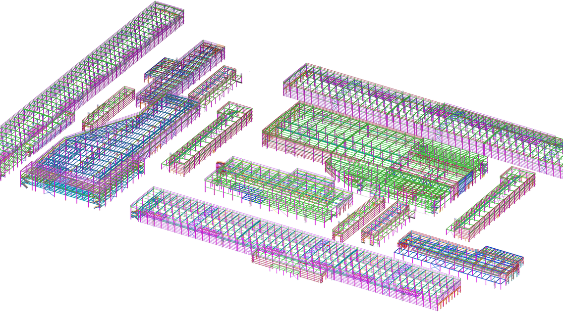
The TEKLA 3D Software is used for 3D modeling of all Depot Structures precisely in line with the architectural geometry and with all structural steel components including steel members, embeds connections, secondary Steelworks etc. The same 3D model is effectively used to coordinate with the stage wise erection engineering methodologies as well as for the coordination & incorporation all around the dome skin. Effective BIM coordnation is carried out by using 3D Tekla Models with all other Trade contractors on the Project.


