Within a development program started in 2013, Finavia invested more than one billion euros to enforce the awarded status of the leading transit airport in Europe, the Helsinki airport in the capital area of Finland. In terms of services and effortlessness, it is considered one of the best airports in the world. The T2 terminal extension project included in the development kicked off in 2017 and is carried out for Finavia by T2 Allianssi.
Instead of separate terminals, it was decided to extend the airport adhering to the one-roof concept which places all new services in one building. Once the development program projects are completed in 2023, the 30 million annual travelers and the 20,000 employees around the area get to enjoy an architectonically glorious airport that provides a pleasant travel experience and an effective air transport node.
An extension in the size of 11 standard soccer fields
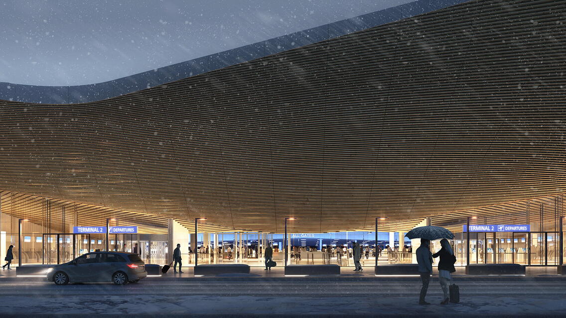
In total, the terminals are extended by 103,000 m2 which increases their size by 45%. An additional 4,800 slots will be available for parking, and a multimodal travel center connecting the various modes of transportation is to join the new departure hall building and the new entrance to the local Ring Rail Line. The air transport infrastructure is being extensively modernized overall: for example, the number of jetways for wide-body aircraft will be doubled, and the apron will be upgraded to cover an area of 450,000 m2. Baggage handling and passport control will each have 50% more capacity.
The Helsinki airport is a pioneer in BIM in Finland
Since 2017, Finavia is a forerunner in the application of the national BIM guidelines in Finland. It is a client with very high goals for the utilization of BIM documentation in facilities management, use of geospatial data, and change management. When the T2 project started, there were high-quality building information models available of the airport that complied with the national guidelines. Moreover, at no point in the project were the benefits of BIM compared with traditional 2D design. BIM benefits have been obvious since 2007.
The project is very challenging due to its scale and complexity. It is a truly hybrid project, the functionality of which during construction is ensured by temporary arrangements. The airport is in use throughout the project, and special attention has therefore been paid to safety, user experience, and communicating site status. There are many interfaces with the old terminal and the deck structures in the area, and the architecture is exceptionally demanding. Additional design challenges included coordinating the apron level with the terminal as well as schedule discrepancies.
Sustainable development and green values
Corporate responsibility and sustainable development are at the core of the client’s business. This means that the client carries the responsibility for its operations’ impact on people, the environment and society diligently and with attention to detail. BREEAM Excellent-level certification applied per the BREEAM Bespoke Process was taken into consideration in the design and construction of the T2 extension. An example of Finavia’s sustainable development advancement, is solar power plants designed and built as part of the development program. Building information models helped in the solar panels’ feasibility analysis and positioning.
Shared responsibility of the models
Effective BIM-based collaboration throughout the project has been the most decisive success factor. The visualizations produced from the building information and composite models have been used in almost all stakeholder meetings, and they have helped engage the project parties and decision-makers in the future construction process and operational development. All designers, the nearly 10 component suppliers who worked on the models, and the contractors were engaged in a weekly model update process that made the management of the more than 400 models needed for the project to run smoothly. The component suppliers’ models, the “virtual safaris” launched during previous terminal extensions, and the combination models that have facilitated permit preparations for the building control and collaboration with future retail tenants all illustrate how exceptionally extensive the model-based collaboration has been.
Real-time digital status as an enabler in the project: frame takt time assembly and scheduling
Another major success, was the demanding frame installation and other construction works were all completed on schedule. The project utilized status information from the model exceptionally extensively to visualize design, fabrication and site progress. BIM-based installation monitoring helped provide an up-to-date idea of the situation on the construction site to all parties once a week. Installation information was entered into the models on site, and this helped produce the PowerBI analyses from which the precast concrete, structural steel, CIP and masonry partitions’ progress rate percentages could be monitored per location. In addition, the as-built model illustrated the installations per week and delays in different colors. The as-built model also highlighted the sections for which the precast or rebar designs were available.
The building frame is precisely scheduled, and the project was able to apply the takt time concept (Lean process) for its engineering – probably as a first in the world. The model was used to determine takt areas and calculate the engineering quantities in each takt unit. The tack areas were created and visualized in the model. This enabled concrete visualization of the units included in each takt area. When structural status including surface work was known in the model, the MEP contractor knew exactly when to start each takt and was able to make preparations if any construction work phase was not yet complete.
An airport, shopping centre and national boundary all in one building
The project includes many more stakeholders to take into consideration compared to normal. The stakeholder groups must provide information for Finavia's decision-making to ensure the functionality of the terminal. Throughout the project, communication with the stakeholder groups was conducted using “virtual safaris”. The building information model, including equipment and signage, and the refined virtual model helped improve decision-making processes and create mutual understanding. The safaris helped request comments and create an open dialogue environment around the project. Mutual understanding created with the help of models made decision-making more democratic. The virtual models were also used as aids to induct new employees in various occupational groups. Observations are received during operative training and field testing by which functionality may be fixed or completed.
At completion, the commissioning and induction processes are key in ensuring the functionality, healthiness, safety and user experience of the airport. When the same people are involved from the beginning, they understand what construction encompasses. Both the users of the premises and the makers of design decisions take responsibility of their development proposals. Based on the received feedback, the route of the departure lobby was made more fluent. BIM and simulation thereof also helped decide the width of traveler routes and the locations of the main frame beams.
In addition, the models helped ensure security camera angles and check sun reflections, based on which curtains were added and workstation locations changed. People with disabilities were invited to participate in the virtual safaris to check the future airport and signs, and sign locations were adjusted based on this feedback.
During the COVID-19 pandemic that lasted for more than a year, the stakeholder groups were engaged in MS Teams. Remote cooperation was fluent and interactive with various stakeholder groups and authorities. The combination model helped advance matters with the Vantaa building control unit when preparing for the building permit and with structural inspection. Modeled structural limitations were easy to present as initial information to the future tenants of the retail premises. The process culminates in the ORAT procedure before the commissioning, during which the stakeholder groups are introduced to the completed premises by also using the virtual model.
A huge number of models
The design team, the component suppliers and the contractors operated in a highly professional and solution-focused manner, and the building information models were the main communication channel for a group of 100–200 designers. The source data for the design consisted of extensive laser scans, the data of which was modified to serve as reference files. The geometry of existing structures was also modeled on the basis of point clouds for the interfaces, for example. The actual installation heights of the roof trusses in relation to their theoretical locations were compared with the scanned data imported into the model.
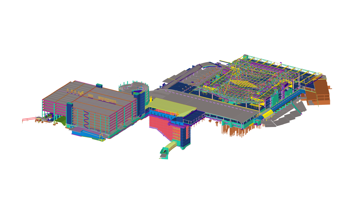
The project is divided into six main combination models, including five construction ensembles and one review model that combines all areas. The platform for information exchange was an online reporting service called BimCollab bcf. For the construction site, the composite models were transformed into the Trimble Connect environment. During the site layout and foundation phase, the combination model was exported to InfraKit software for the machine control models.
Since the beginning of the project, the combination model was used to cross-check the infrastructure and the building solutions. The project included planning demanding traffic arrangements and the phasing of working-time traffic arrangements as well as the design of infrastructure networks. The completed models were exported to the combination model in IFC format, and InfraBIM standard material was delivered on-site for the machine control models. The composite model was also used to make an instructional video for site logistics, including supply delivery locations and transport routes.
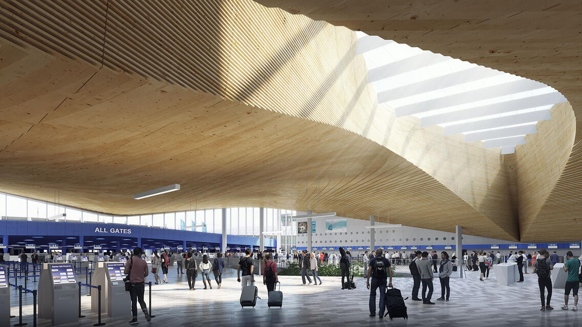
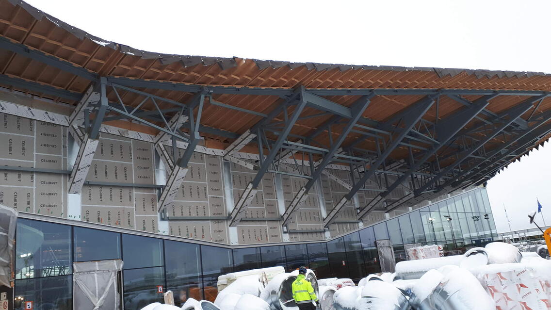
Construction coordination was mainly based on the architectural, structural, MEP and supplier models. For example, regarding the impressive and challenging wooden ceiling in the departure lobby. The architect used algorithm-aided design to model the undersides of the ceiling, and the component supplier modeled the ceiling dimensionally accurately so that its components and fasteners could be matched with the frame. The model of the ceiling was exported to use as input data for manufacturing and served as the basis for production management. MEP equipment was coordinated and installed between the ceiling grids.
Chewing up the software
In total, more than 30 BIM-related software products have been used in the project. In addition, algorithms and programming tools have been used to aid the modeling, the models have been enriched for various purposes, and missing interfaces have been created by programming. The advanced project team, open alliance culture and use of open standards have enabled the use of appropriate tools and, when necessary, new developments for the benefit of the project.
Fire safety design was provided by L2 Paloturvallisuus Oy. For this, the building information model was imported in IFC format to the simulation software. BIM use was not limited to fire simulation but was also plenty of help in the model used in the simulation of the escape routes. The various rooms, floors and connecting stairways as well as exits could be designed close to a tee. In the past, matters related to geometry, such as stairs’ vertical rise and horizontal thread always needed to be checked in the floor and sectional views or calculated by hand. BIM reduced the workload as there was no need to re-model the structures created by the architect. In addition, modeling helped make fire design more precise.
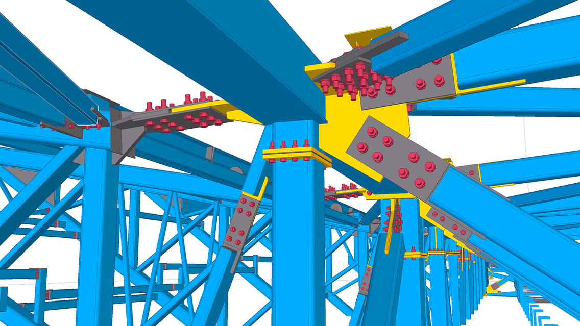
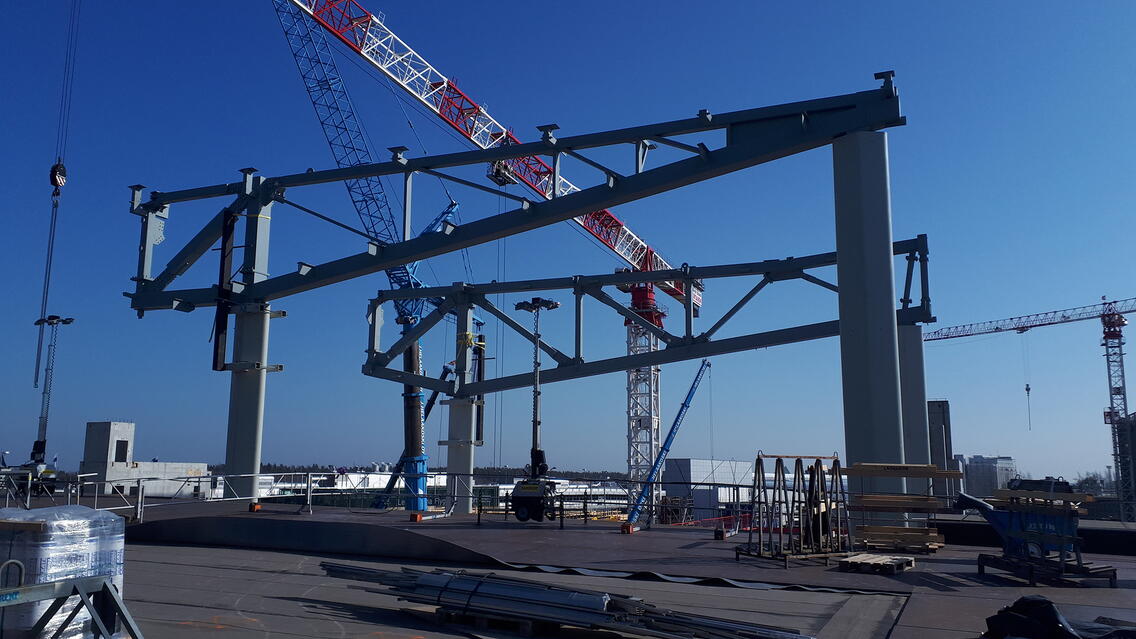
All models were Tekla Model Sharing models, and over the entire project, the terminal model alone involved more than 100 users from eight different organizations. The level of detail in the modeling was high. Both CIP and most of the precast reinforcements and casting accessories were modeled. The large, impressive steel truss on the roof was also modeled including all its details. The hole reservation process was also carried out based on BIM. In addition, several components were programmed for Tekla Structures, such as a macro that could run a DWG file for the excavation contractor’s machine control “at the touch of a button”. The foundations were updated several times, so the macro was an excellent solution for this purpose. Pile lists and locations as coordinates and complete lists for machine control were also obtained directly from the model.
Building component suppliers modeled exceptionally actively in this project and played an important role in the coordination process. For example, Delta Beams, ventilation chambers, compartmentalized mechanical rooms, the wooden ceiling of the departure lobby, thermal facade units, Ring Rail Line facades, parking garage facades and aluminum elements, roof elements and parking garage precast units were modeled.
Change management “at the push of a button”
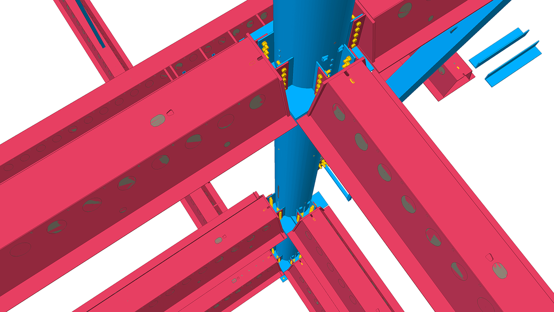
The architect’s model was used as input for structural design and received as a Rhinoceros file. From Rhino, the geometry was taken by using algorithms for FEM analysis and the Tekla model. During the development phase, the input data often changed, for example regarding the size of the terminal, so the use of algorithms was necessary to stay on schedule. Once the structures were dimensioned based on the force quantities of the FEM model, they were sent to Tekla Structures using Ramboll’s own C# program and Tekla Open API. The bar data was stored in C#, and a link was created between them and the bars in the Tekla model. This way it was easy to update the bars in the Tekla model once the source data changed. In the steel detailing phase, similar algorithms helped dimension the joints based on force quantities and re-model in Tekla Structures via the Open API.
In the development phase, the roof shape was analyzed algorithmically in terms of rainwater runoff and wooden elements chosen for the flat roof.
Project parties
Owner: Finavia Corporation
Structural design, HVAC design, electric design, traffic planning, infrastructure engineering and foundation engineering: Ramboll Finland Oy
Main contractor: SRV Rakennus Oy
Principal and architectural design, interior design: ALA Architects Ltd.
Principal and architectural design: HKP Architects Ltd.
BIM coordination: Gravicon Oy
