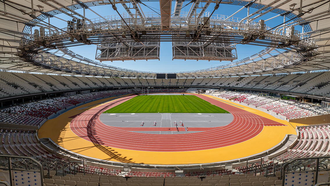
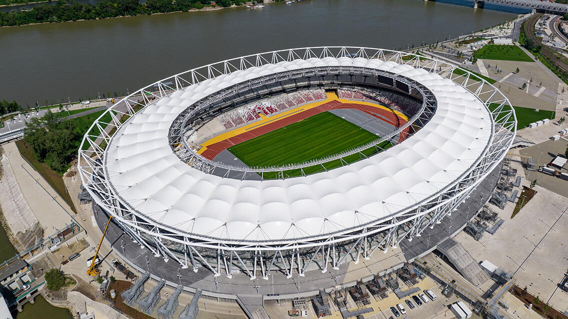
The new Budapest Athletics Stadium, serving as the central venue for the 2023 Athletics World Championships, is located south of the Rákóczi Bridge in a triangular area enclosed by the main branch of the Danube River, the Ráckeve-Danube branch, and Kvassay Jenőút.
The tasks of BIM.GROUP was to prepare the technological manufacturing, and installation drawings for the steel and cable structures, supporting the manufacturing, assembly and geodesy processes throughout the realization of the building, as well as to coordinate the work of the involved specialist partners.
DESCRIPTION OF THE ROOF
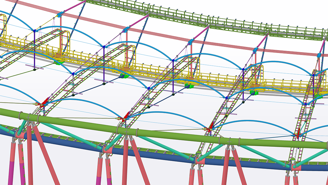
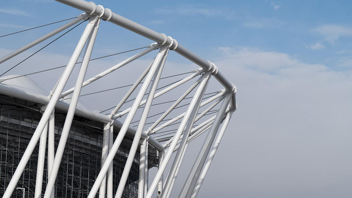
The roof is designed as a prestressed cable structure with two inclined outer steel compression rings, two inner cable tension rings placed above each other, and 48 radial lower and upper cables. The lower and upper cable systems are offset from each other by vertical rigid steel compression struts. The compression rings are supported by inclined outer and inner steel columns, forming a crown shape. The roof structure is covered with prestressed membrane cladding.
In addition to the primary structural system, secondary steel structures have been designed: rotating, curved, prestressed purlins, a lighting rig, lower and upper circumferential gantries with retractable bridges, 4 LED screen support structures, self- supporting gutter, and a complex cable tray supporting system.
The equilibrium shape results in a saddle, causing the geometry to vary from grid to grid, with slight differences of a few centimeters and tenths of degrees between similar assemblies.
MODELING OF COMPRESSION RINGS
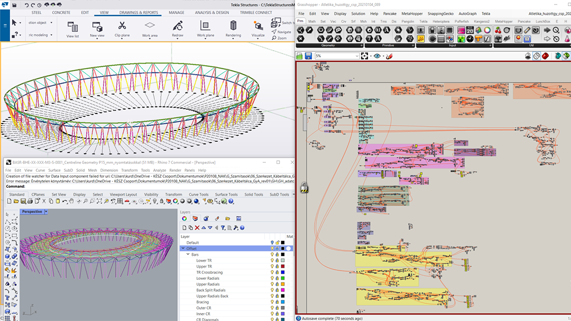
The characteristic of the prestressed cable structure is that the structural shape is a result of equilibrium calculations and is iterative. In Tekla modeling, a specific workflow was needed where the wireframe geometry could be modified, and the model could be updated. For this purpose, the Rhino-Grasshopper software with the Tekla Live Link plugin was particularly suitable. By replacing the wireframe and rerunning the algorithm, the Tekla model could be regenerated to the shape corresponding to the current structural calculation.
The equilibrium geometry of the prestressed cable structure cannot be directly used for fabrication. To determine the manufacturing lengths of individual elements, it was necessary to compensate for beam lengths based on internal forces. Separate wireframe models were created for different states (manufacturing shape, assembled compression ring, prestressed cable structure, completed roof), and by loading them in the Rhino-Grasshopper software environment, the Tekla model could be generated for the corresponding shape.
The manufacturing and installation tolerances for individual assemblies were very tight, (±3mm on a 20-30 meter length product). To ensure this, detailed evaluations based on laser tracking measurements were conducted during and after manufacturing using precise STP files exported from the Tekla model.
The compression ring was erected from 48 diamond-shaped pre assembled units. These are topologically identical, but their precise geometry varies by a few centimeters. The diamonds were assembled in a mounting frame with “adapter” components corresponding to each unique position. The diamond, together with the mounting frame, was delivered to the center of the stadium, after being lifted, was rotated into a vertical position and inserted into its final location.
MODELING OF CABLE STRUCTURES
The complex cable structure nodes contain many specialized machined details (e.g., funnel-shaped cable outlets.) Therefore the modeling of the cable structure was done inRhino by the cable supplier. These models were also needed in Tekla., therefore “item.”type Tekla objects were created from the native Rhino objects using the Tekla Live Link, which we then exported to a separate IFC reference file.
MODELING OF SECONDARY STRUCTURES
The specialty of the curved purlins is their rotation capability around their axis on the machined rods, standing out from the cable nodes. One end of the curved elements can be installed with a horseshoe-shaped end plate, which can later be secured against fall-off with a special machined fixing element.
To model the cantilever joints for the gutter on the lower compression ring on the fabrication geometry, we had to properly calculate the movement and rotation effects of the cable prestressing to ensure that the final gutter geometry after the movements would be horizontal.
For the roof structure maintenance, circumferential walkways and two motorized bridges were designed. The lower walkways are connected to the lower ring nodes, with connections allowing sliding and rotation. The upper walkway is supported by a tie-strut cantilever. At 4 locations, there are dilation joints with bearings allowing ±20cm longitudinal movement. The inner end of the movable bridge connects with a bi-directional pinned connection to the lower walkway. The outer end is fixed on a podium suspended from the curved purlins. The bridge can be lowered with motorized chains to the concrete stand.
Four LED screen-supporting structures, each measuring 115 m2, were built on the upper walkway. The structures were pre assembled on the ground horizontally and lifted as a whole, with rotation during the lifting process. A challenge was posed by that the center of gravity of the structure is under the upper walkway, requiring the use of a C-shaped temporary structure to allow it to be inserted under the walkway without lifting reeving.
Between the compressed ring and the lower walkway, 48 complex cable tray support structures were installed on the radial cables. The structure had to be designed to avoid altering the primary cable structure forces while allowing significant movements and angular rotations during service while maintaining stability in all conditions. Vertical force transmission occurs at separate cable nodes on the upper cable, while in circumferential and radial directions support is provided on the vertical struts using vertically sliding “LEGO arm” connections. The sections between the vertical struts are designed with connections allowing ±20 cm movement and rotation. It was also necessary to ensure the precise horizontal positioning of the structure in a circumferential direction with length – adjustable suspension rods.
Project parties:
Architect: Napur Architects Ltd.
Structural Designer: EXON 2000 Ltd.
Steel Structural Designer: bim.GROUP Ltd.
Cable Specialist Designer: BuroHappold Engineering Ltd.
Peer Reviewer: Schlaich Bergermann Partner, Nyomásvonal Ltd.
Cable Structure Detail Designer: Maffeis Engineering Spa
Tekla drawings: The Engineering Design, DB Engineering
Client: Beruházási, Műszaki Fejlesztési, Sportüzemeltetési és Közbeszerzési Zrt.
General Contractor: ZÁÉV and- Magyar Építő Consortium
Cable Lifting Designer: Sclaich Bergermann Partner
Rigid Steel Manufacturer: KÉSZ Ipari Gyártó Ltd., Weinberg 93 Ltd.
Rigid Steel Erector: KÉSZ Metaltech Ltd.
Cable Manufacturer and Erector: Teufelberger Redaelli
Cabel Lifting Specialist: VSL
Geodesy: GeoLink3d Ltd.

