The road from Ranheim to Værnes.
The Ranheim to Værnes leg of the E6 highway is 23 km long. It will be expanded from two to four lanes to improve the flow of traffic, reducing the need for detours as well as improving customer safety. This new infrastructure is aimed at improving connectivity in the northern part of Trøndelag County in central Norway.
The project consists of an upgrade of a 23-kilometer-section (between Ranheim to Værnes) of the E6 highway, including three tunnels and multiple structures.
The route follows the old road, with the exception of the tunnels, which will run parallel to the existing ones.
From the multiple structures that conform to the project, we will focus on:
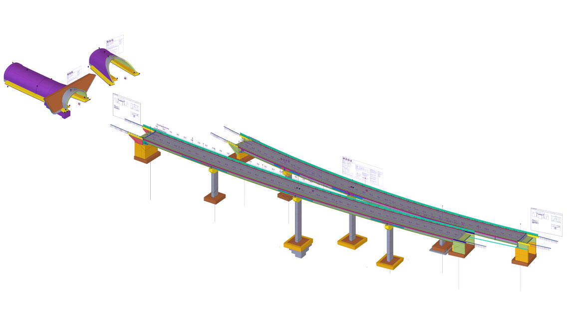
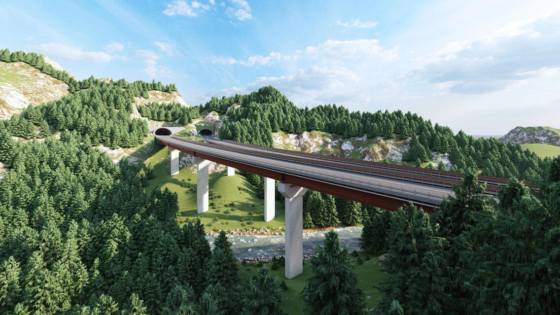
- Hommelvik viaducts: The structures are 240-meter-long composite bridge girders composed of two welded longitudinal steel beams which support a 15-meter-wide deck. These bridges are based on five axes: two abutments and three rectangular concrete columns. Regarding the foundations, footings are used to transmit the bridge loads to the terrain.
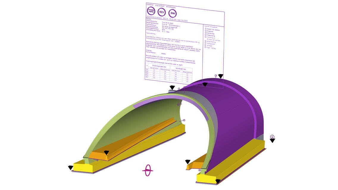
- Portal Stavsjøfjell southbound: The structure consists of a 60-meter-long monolithic-in-situ-concrete structure. The first 40.50 meters are based on a constant 0.60-meter-thick vault section which starts to widen until it achieves a trumpet-shaped geometry.
- Portal Stavsjøfjell northbound: The structure consists of a 31,5 meter-long monolithic-in-situ-concrete structure. The first 2 meters are based on a constant 0.40-meter-thick vault section which starts to widen until it achieves a trumpet-shaped geometry cut by a sloping surface.
Main figures for these structures
- +15300 m3 of structural concrete
- +1760 Tn of structural steel
- +2250 Tn of reinforcement steel with +150.000 rebars
- +6000 Welds
- +650 Bolt groups
- +23000 Tekla objects
Methods and tools
An integrated model-based design has been implemented in our way of working. A special focus was added to design optioneering and added value solutions for an efficient data handover for construction and operation purposes. This has been achieved through a close collaboration between the ACCIONA Engineering team with the various stakeholders involved in the design, review, approval, and construction process. This is all against a data-rich model where teams can review and extract information.
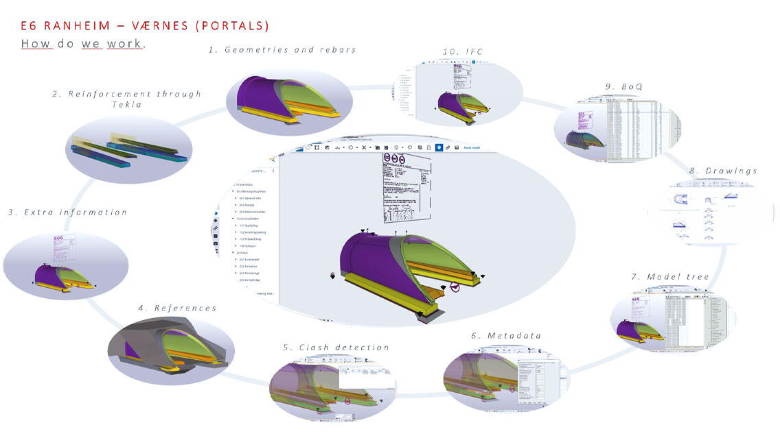
The viaducts and portal structures are not lineal and are defined through very variable geometries on the x, y, and z-axis. We have used a combination of parametric design in Rhinoceros/Grasshopper and Tekla Structures for the definition of the structural elements. Parametric design is used to input the design criteria and calculation parameters and to generate geometries like polylines, points, and meshes. These geometries are transferred into Tekla Structure as native Tekla objects such as slabs, walls, steel girders, connections, etc., with all their properties and characteristics. This allows us to further develop the model with all Tekla functionalities and work with structural objects that can be used for drawings generation, quantity take-off, IFC export, etc.
The following points are the main methods implemented for each structural type:
Viaducts
- The concrete deck and its reinforcement plus the steel deck structure have been created first through parametric design, including Grasshopper. The work was then transferred into Tekla for further usage.
- The abutments, columns, pier caps, and foundations, including all its reinforcement, have been done directly in Tekla with modeling tools and custom Tekla components.
Tunnel portals
- Concrete structures and reinforcement have been created through parametric design, allowing us to generate multiple design alternatives with all the different variables and width and longitudinal variations. All the geometries of the tunnel portal and the reinforcement of the vault have been modeled through parametric tools, including Grasshopper. The geometries have been transferred into Tekla for further usage.
- The reinforcement of the foundations and the barrier has been done directly in Tekla.
In addition to graphical detail, information is also key in ensuring the right data is captured during the design process to be shared for construction and operation. A complete set of attributes was identified and implemented across all the model objects, including project data, structural data, “process mode,” and asset codes such as Brutus and Class. Also, an information box has been placed on each of the structures with key information for a more comprehensive data interrogation through the model.
The E6 Ranheim-Værnes has a special emphasis on how to build a safe and sustainable infrastructure. For that purpose, any risk related to each structure is included and highlighted in the model to facilitate risk identification and communication among the teams.
Collaboration
Developing the kind of structures that are based on geometry and inputs from other disciplines such as road alignment, road safety design, geotechnics, drainage, and tunnel, requires an efficient way of exchanging information and close coordination and collaboration between the different parties.
Trimble Quadri has been implemented in the E6 Ranheim-Værnes project as the main coordination environment for model federation and interdisciplinary coordination.
Internally within the ACCIONA Engineering team, we also implemented Trimble Connect as the focal point for information exchange between structural, modeling, drafting, and project coordination teams. All the external references needed are in Trimble Connect with up to 10 Gb of cross-shared data.
IFC file formats are exported from Tekla Structures into Trimble Connect on a regular basis for teams’ coordination and review. When ready, they are transferred into Trimble Quadri.
Model collaboration has been managed through Tekla Model Sharing, ensuring live collaboration between team members.
The benefits of using BIM and Tekla software
The implementation of BIM tools, methods, and processes enabled digital information to become a key for decision-making, collaboration, coordination, data exchange across teams, and asset handover. The integration of BIM into the design activities and its outputs for construction activities and supplier/manufacturers supports project delivery and provides a legacy of graphical and non-graphical information while driving efficiencies during the project lifecycle.
With the use of more efficient tools with parametric design tools and Tekla Structures, we improved the way we collaborate and communicate and accelerated the review and approval process. Design and build conditions review processes and clash detection workflows have been implemented, allowing early identification of design constraints between disciplines.
Benefits of using BIM methodology and Tekla Structures
- The viaducts have a composite structure (concrete and steel) and really challenged our team in the initial phases of the design and in the modeling process. The use of parametric design tools allows more interactive optioneering with multiple solutions to find the most efficient design. The parametrization provides a more efficient reaction to the common changes and challenges that occur during the design process.
- The concrete structures for the viaducts and portals require a high density of reinforcement that need to be manufactured and placed on site. All the rebars have been split into different numbering series depending on the construction phase to make their manufacturing easier. Moreover, rebars with complex geometries have been correctly identified in Tekla Structures and modified in the rebar shape manager. Thanks to these processes, BBS and BVBS files have been prepared by ACCIONA Engineering in coordination with ACCIONA Construction and its suppliers/manufacturers for the most efficient data exchange from design to construction.
Main stakeholders that use the model
- ACCIONA Engineering: native Tekla Structures, parametric design tools, and IFC export files from Tekla Structures
- Ramboll (co-designer and structures controller): IFC export files from Tekla Structures
- ACCIONA Construction (Contractor): IFC export files from Tekla and native Tekla file
- COWI (3rd party control): IFC export files from Tekla Structures
- Statens Vegvesen vegdirektoratet (Norwegian road authorities): IFC export files from Tekla Structures
- Nye Veier (Project owner): IFC export files from Tekla Structures


