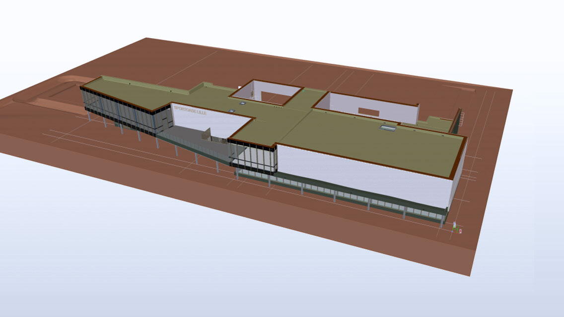
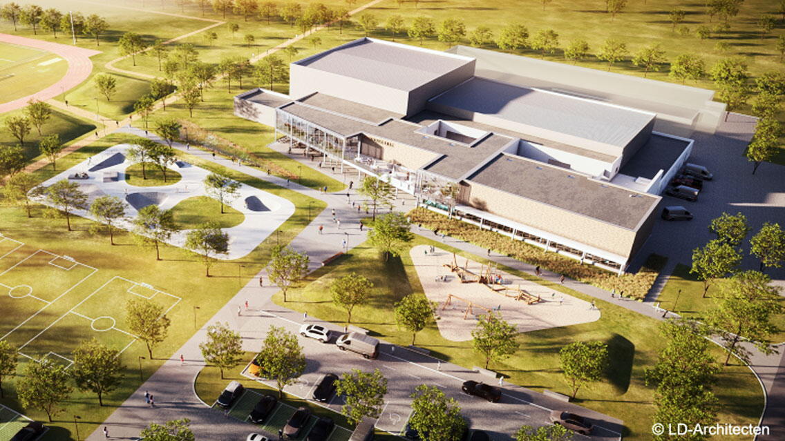
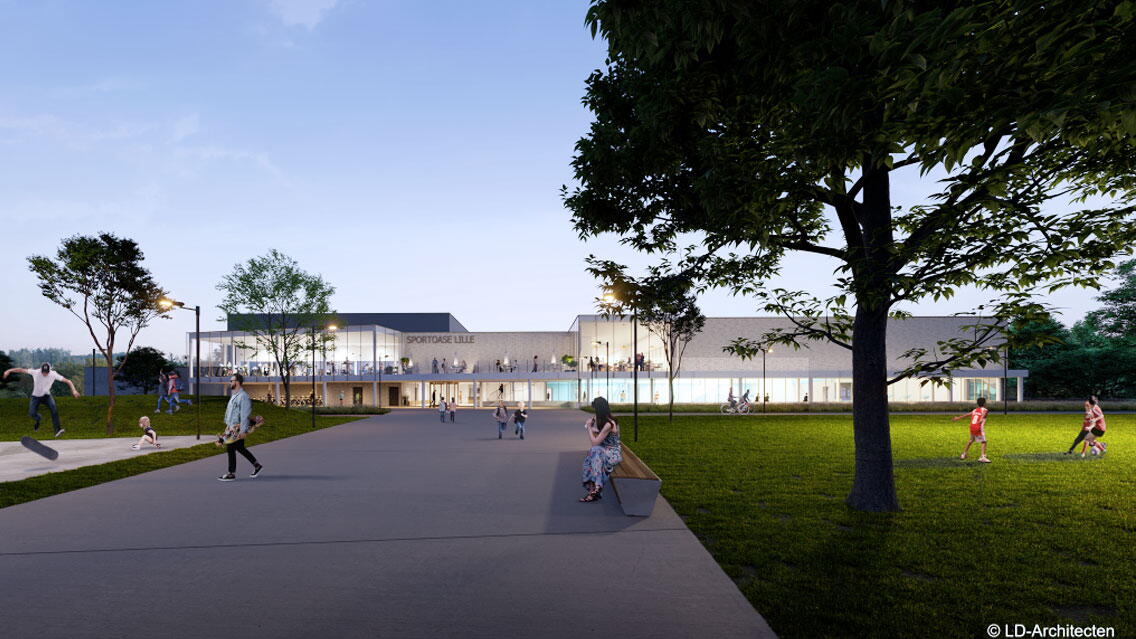
The project concerns an extension to the sports complex in Lille, France, on the site of the Balsakker sports center. This extension includes a swimming pool, cafeteria, and fitness area. The swimming pool contains a large 25m pool with a movable floor, a paddling pool, a slide, and a wellness center with adjoining changing rooms and lockers. The new cafeteria connects to the cafeteria in the existing complex. The extension is structurally separate from the existing building.
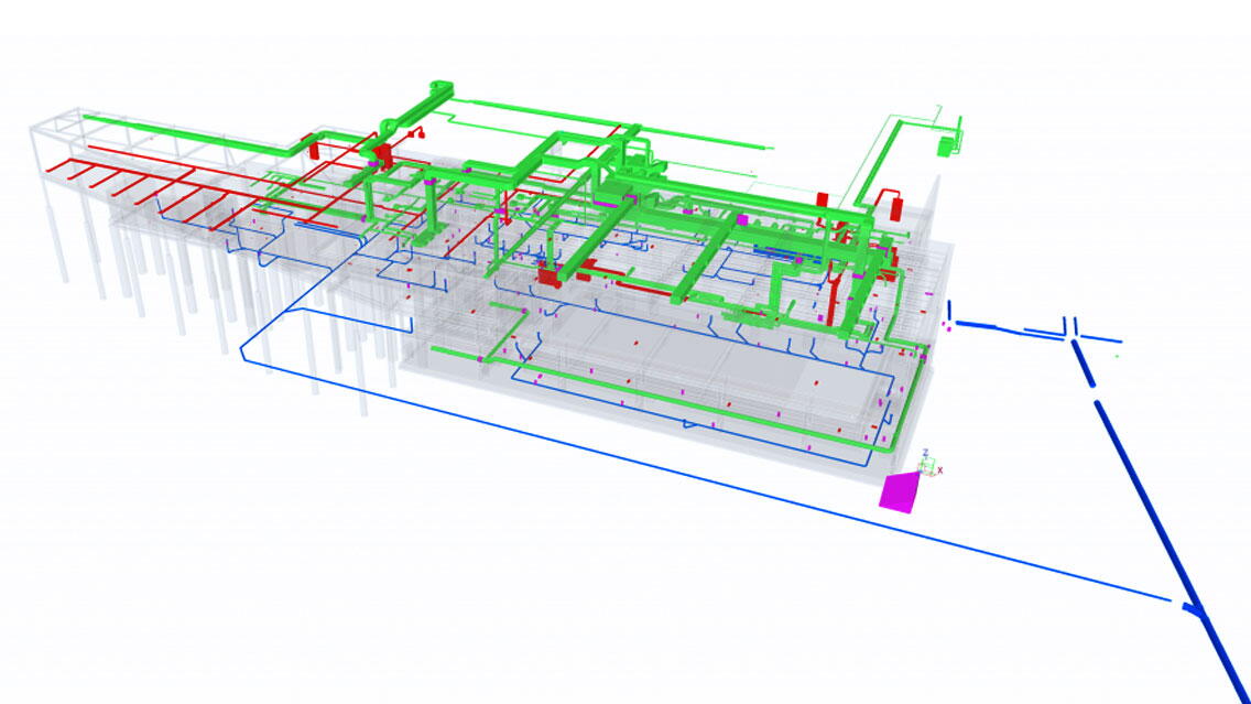
This project required a multi-disciplinary assignment and an integrated BIM approach from the engineering office Tractebel.Tekla Structures was used from the start to model the structures (concrete, steel, and wood). The different 3D discipline models were brought together in BIM 360 and managed by the contractor Groep Van Roey. The 3D IFC architecture models and various techniques (HVAC, electricity, plumbing, sewerage, and water treatment) were also loaded into the model. LD Architects supplied the 3D IFC architecture model. Tractebel designed the engineering model up to LOD200. Models were then developed to a higher LOD by the executing contractors.
This approach allowed all interfaces between the various design disciplines to be properly visualized. It quickly became clear that the various engineering disciplines would play a prominent role. The size and complexity of the pipe network in a swimming pool are considerable. This created the need to provide the necessary cutouts in the structure as early as the design phase. The technical designers provided IFC models with dummy elements that defined the dimensions and position of the recesses. These dummy elements were converted into native Tekla objects, which made the provision of the right cutout in the right place a breeze.
BIMcollab was used to facilitate coordination between the models of the different parties. This platform enabled model review by linking actions to clashes.
Clash detection is done in the design phase, which prevents problems during execution. Moreover, the design team used a 3D model as a communication tool and visualization tool, allowing stakeholders to follow the design closely.
Regarding the structural discipline, the entire formwork was worked out in 3D. Deliverables such as formwork plans and measuring sheets could then be easily generated from the model. After the formwork was finalized in the Tekla model, export to the analysis program Scia Engineer took place. For the exchange, the Scia AutoConverter was used. Next, the analysis model was used for the structural calculations.
In conclusion, coordinating the models of the different disciplines requires some more effort and work in the design phase but is compensated for in the execution phase.


