Project description
Floatgen, the new generation of windmills offshore. The Floatgen project embodies the new generation of French windmills offshore: the floating windmill. This first floating windmill of 2 MW was just anchored at 20 km offshore from Croisic, at the testing site christened SEM-REV of the Nantes l’École Centrale [Central School] for an initial duration of two years.
The electricity produced from this will be injected on the electric network throughout the duration of use. The windmill will provide the equivalent of the annual electric consumption of 5,000 inhabitants. Under the Floatgen European project (supported by the European FP7 program, as well as by the ADEME in France), in partnership with Ideol, Bouygues Travaux Publics is in charge of modeling the frame and the construction of the float.
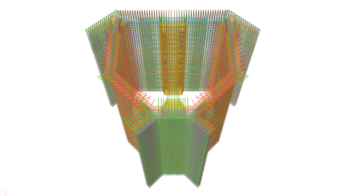
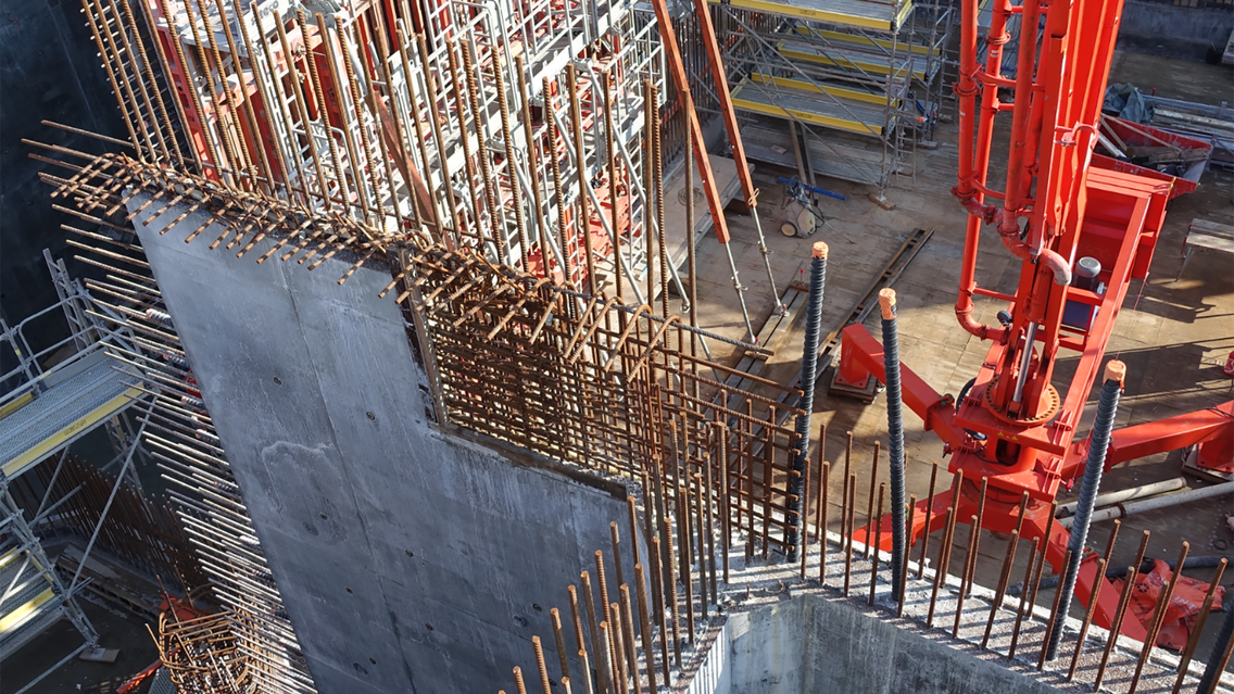
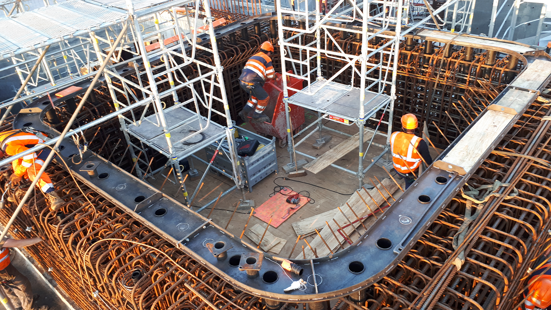
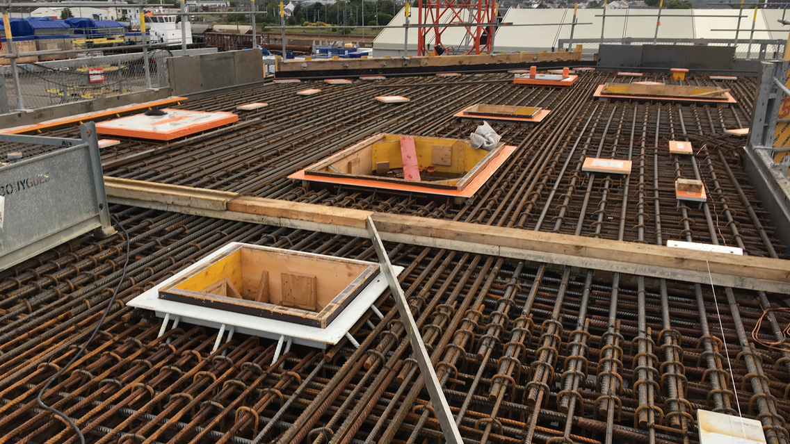
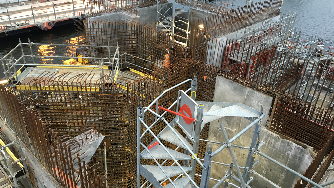
The structure of the float for the Floatgen windmill, measuring 36 meters sideways and 9.5 meters high and fitted with an opening in its center is composed of a floor, structural walls, partitions dividing the box into various cells, some of which are ballasted and with a covering slab. The specific situation for the project leads us to use a marine vocabulary: the walls are named according to their bow, stern, port and starboard; the covering slab is designated "bridge" like on a vessel. Furthermore, the hydrodynamic performance of the float (movement, acceleration on swells) support of the windmill are essential for achieving the project's objectives. Due to this fact, the weight profiles of the concrete float, as well as the position of its center of gravity (or center of buoyancy), that directly conditions these performances, was the subject of particular attention.
The inauguration of the windmill took place in October 2017; it went out onto the water on April 30, 2018 to meet its anchoring point. All publications as well as the description of the project are available on the web site: http://live.floatgen.eu/fr
What were the challenges encountered that contributed to the project's success?
This project represents the first 3D reinforcement performance study from the BYTP office conducted entirely in Tekla Structures. The first challenges encountered were training the teams on the tool and implementing work methods for "multi-users". Thereafter, it was necessary to create the "Firm" at the start of the studies and update it progressively with the personalization of the software environment based on our internal reinforcement processes. This work brought us consistency and homogeneity among all of the modelers.
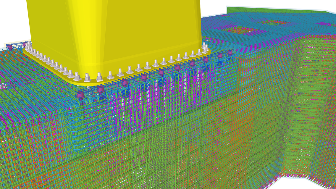
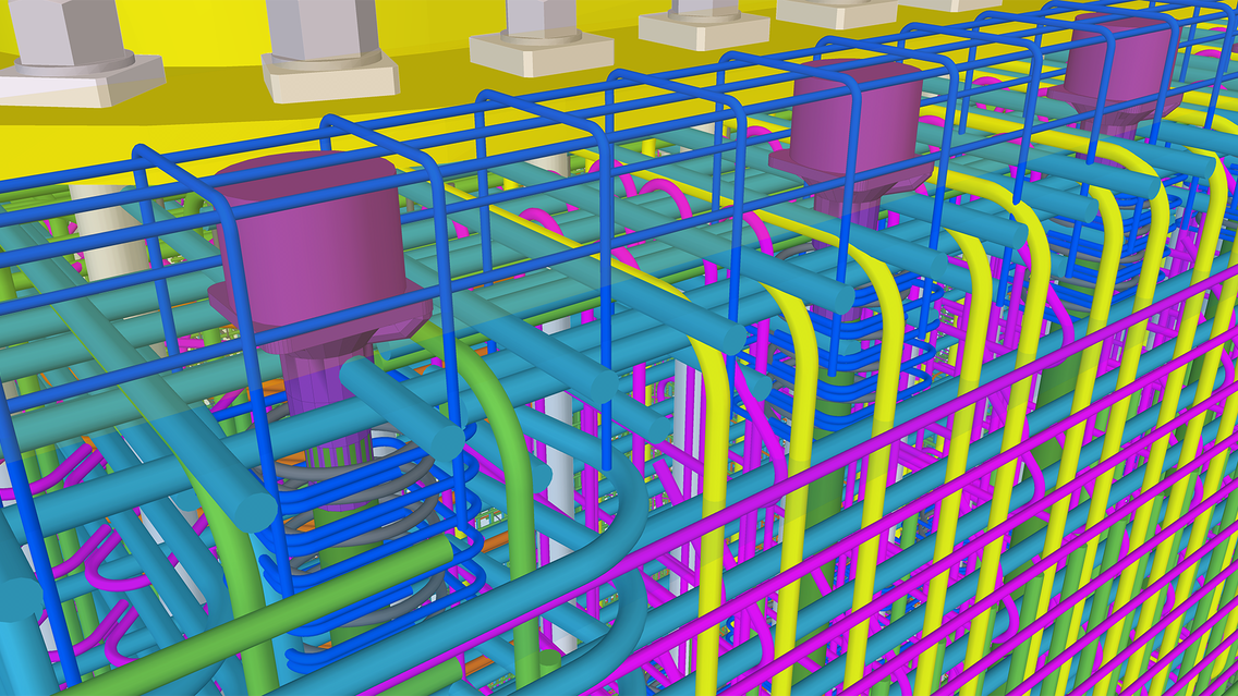
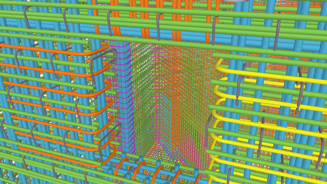
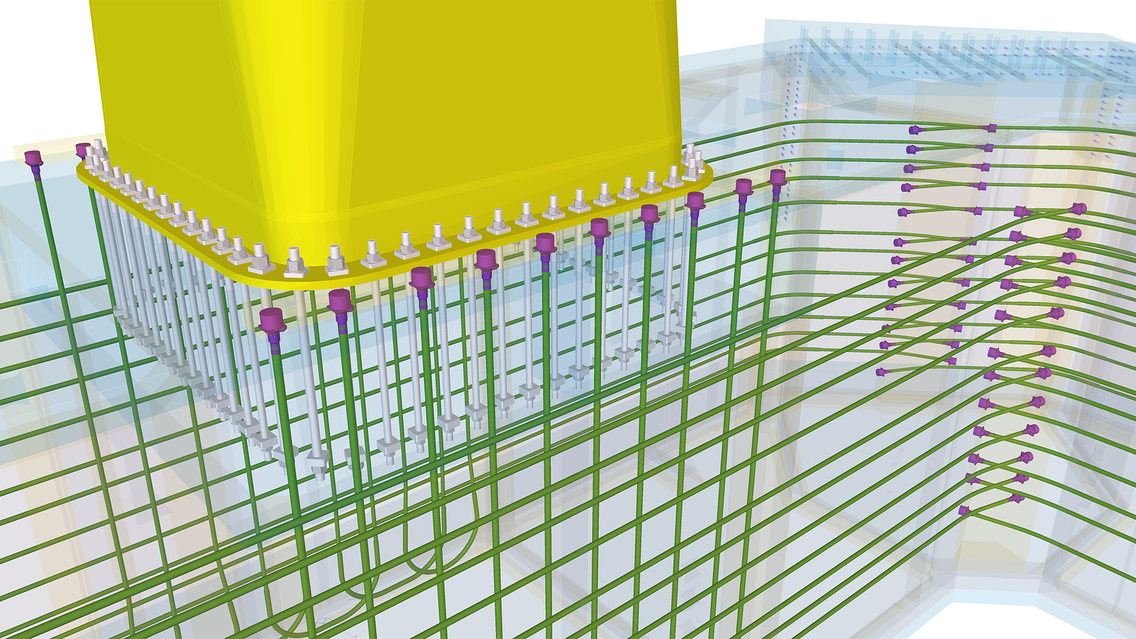
The precision that 3D modeling requires in steel and pre-stressed cables enables us to design the reinforcement of very heavily armed reinforcement cages (on average: 400 kg/m3) without any collision between the steel parts or between steel and pre-stressed cables. However, this high density imposed upon us time-consuming drawing layout in the designs for concrete components, but we were able to submit to Trimble a certain number of iterations in order to improve this process (iterations that were in part integrated in the final version of Tekla Structures 2018).
Finally, we created explanatory videos for frame assemblies that were highly appreciated by the work site, since they facilitated understanding of the frames to be installed. However, the creation of these videos required the export of the mock-up to process the frames outside of the Trimble solutions (Autodesk Navisworks + Microsoft Movie Maker).
What benefits did BIM and Tekla Structures provide to you?
Bouygues Travaux Publics (BYTP) is responsible for the construction of this pre-stressed reinforced concrete float, as well as the implementation plans for form facing and reinforcement. Benefiting from the development of the 3D reinforcement process on Hinkley's EPR in England (in which Bouygues Travaux Publics is participating), the BYTP Design Office chose to use Tekla Structures Rebar Detailing at the start of the project. By using Tekla Structures' multi-user mode, we implemented collaborative work contributing to a unique mock-up: 3 modelers reinforced the float, which was a first for the BYTP Design Office, requiring the correct definition of collaboration rules. This method of work also enabled adhering to very tight deadlines.
The 3D steel model rendered ("raw envelope model") was provided by Ideol in Inventor format, which was translated into STEP format and integrated into Tekla Structures as a reference model in order to be refined and reinforced. The benefits translate, first, by the success of the project and the satisfaction of Tekla Structures' users, in order to reinforce the dense areas (even if that is not always so easy!).
A major benefit was being able to quickly exchange with our partner Ideol in order to provide it, progressively from the design of the 3D reinforcement, the weight of frames per cell in order to check the center of gravity of each cell, the overall weight and the buoyancy point, all while following the changes in the envelope model. Another indirect but very relevant benefit is the alignment of the calculations engineers and "reinforcement modelers" that continuously interacted on the design of frames in order to quickly and efficiently find optimal solutions in complex and dense areas. This contributed to the efficiency of the Design Office compared to a classical production process of 2D plans that are then reviewed and corrected. The use of the Tekla BIMsight viewer on the site enabled the work conductors to understand complex areas and implement with the frame installer.
Finally, we appreciated the involvement of the DEXTRA company (manufacturer of frame couplers) that developed its library of couplers on the Tekla Warehouse, integrating into the generic tool developed by Trimble.
