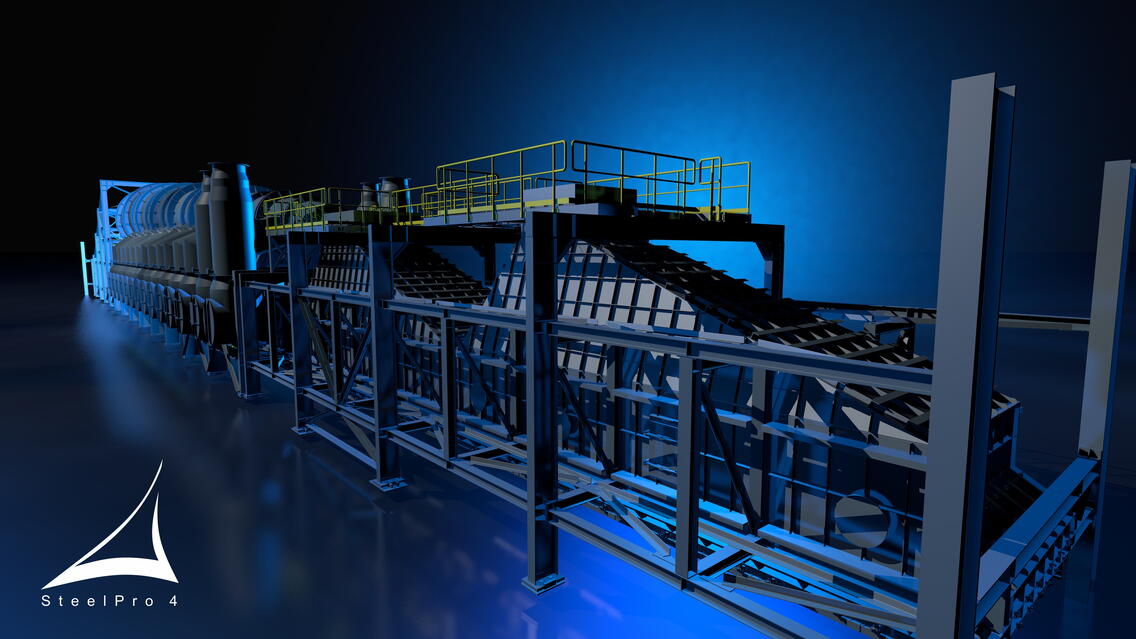
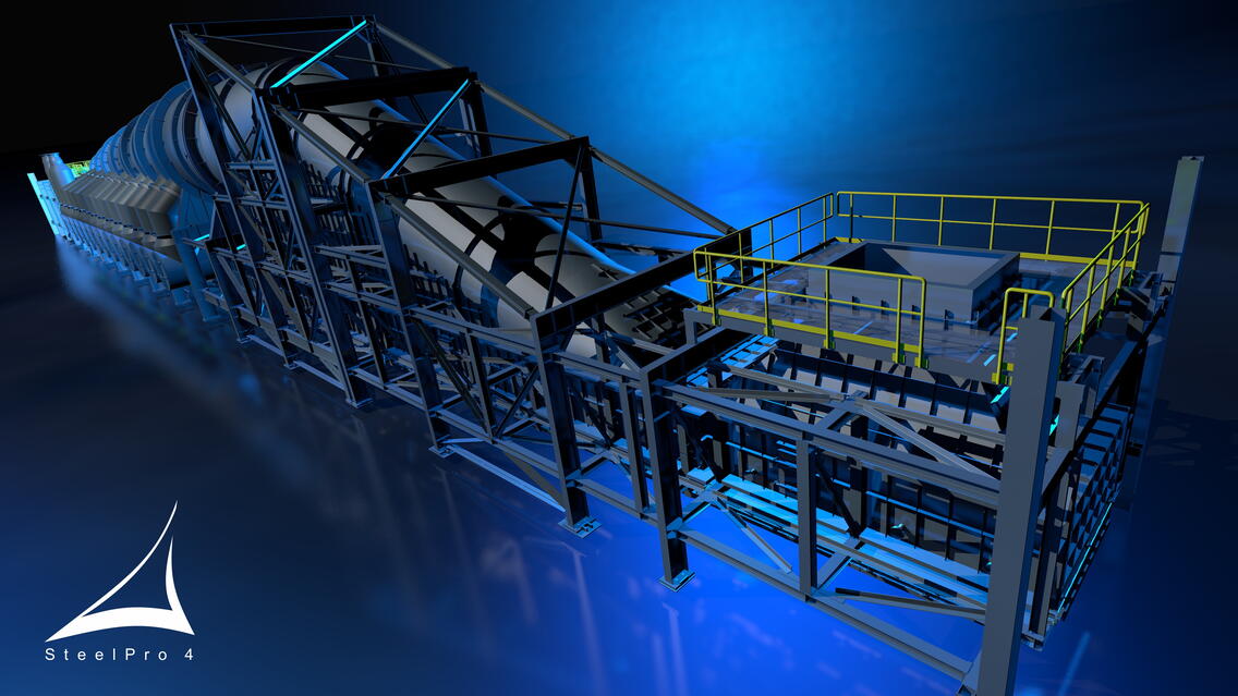
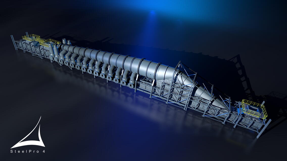
The scope of SteelPro 4 s.r.o. delivery was the static design of the complete structure of the indurating hood (steel structure including all sheet metal parts), creation of the 3D design model, preparation of design drawings showing the lining, and then creation of production and assembly drawings according to the customer's requirements.
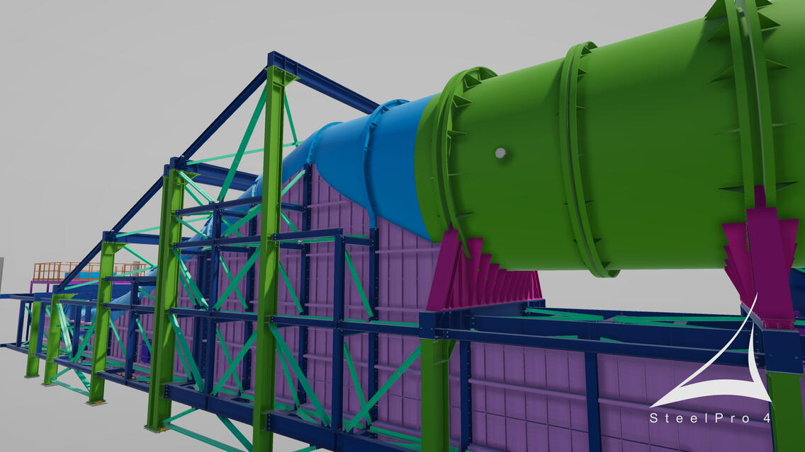
An indurating hood is a separate object in the building, which is used for the processing of iron ore, where the resulting product, after quenching in an oxidizing atmosphere at a temperature of 1250°C, is the so-called "pellets." The object is divided into 3 three units and is anchored by hinged joints at the level of +8.985m to the columns of the main building. All anchoring takes into account the thermal expansion and seismic effects of the main building. The steel structure was designed as bolted, the sheet metal parts of the duct are attached to the columns taking into account the different thermal expansion of the connected parts. The recuperation duct (conical tube) was designed as an all-welded on-site duct with a fixed-slide-fixed bearing system. Downcomers for air supply from burners are designed as welded parts in the shop with needed alignment and the final position is welded on site. Auxiliary structures for transportation and assembly were not included in the scope of supply.
To create the 3D model and drawings we have used Tekla Structures Steel Detailing. The elements of the recuperation duct and downcomers were modeled using the lofted plate function, combined with modeling in Rhino Grasshopper.
The submitted documentation was designed as multi drawings for parts and items, submitted in *. DWG / *. PDF format. For the DWG files, it was necessary to use a stamp with predefined blocks for further "machine" processing on the client's side, which had to be solved by creating an external application. The challenge was the reports on the assembly and production drawings, where, for a while it was not possible to reconcile listings with different hierarchies. A separate chapter was meeting the requirement to automatically display a different scale of individual views, sections, etc., than the basic scale of the multi-drawing itself.
Inconsistencies in dimensions / cotations (1 mm difference in values) between one total cotation and the manual sum of the chain cotations caused significant problems with the generation of item descriptions, reports and the cotations on the drawings, as differing values were not tolerated, and in many cases the cotation values had to be cross-checked and adjusted.
One of the important requirements was the exchange of 3D models. With regard to the requirement for output in *. STP format, it was found that it was only realistic to meaningfully export straight elements without curves. After a consultation with Tekla support, an official statement to this matter was issued and forwarded to the client. The client was forced to remodel the curved elements for their work and in other cases these elements were not included in the export.
As a minor detail we can mark the complete redrawing of the developed shapes of the recuperation duct and downcomers. When using the lofted plate function, it is not possible to create a "mesh" for the dimension of the unfolded shape. The entire system of auxiliary lines and values was completed manually. For the mitre-cut elements, it was necessary to manually adjust not only the shapes but also the plate values in the descriptions and reports.
This project was a challenge for our company both in terms of static calculations and detail design and the correct creation of the 3D model and the subsequent drawing part. It was necessary to understand the process itself, correctly apply various details to "seal" the hood, ensure its thermal expansion, and take into account the requirements of seismicity.
Thanks to a great team and really great support from the client, this task was accomplished, and we believe that we will be able to capitalize on the newly gained experience on another similar project.


