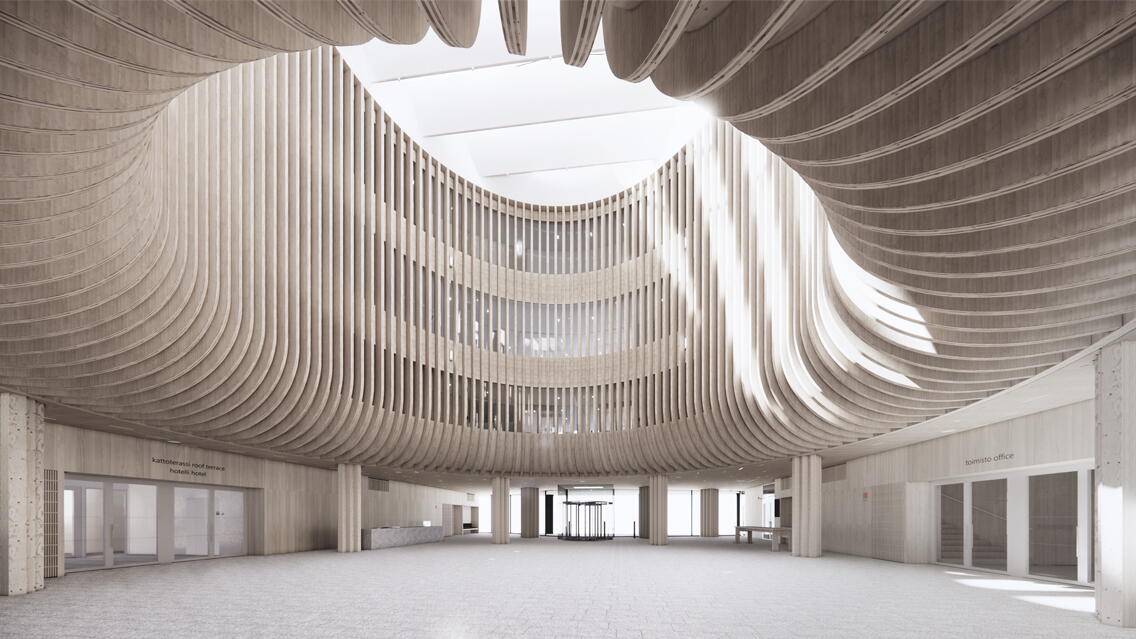
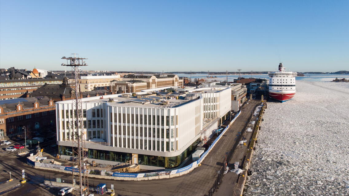
The project commissioned by Varma Mutual Pension Insurance Company is a modern commercial building with comprehensive services for both hotel and office users. The South Harbour is part of the iconic national landscape of maritime Helsinki, which is being developed with an understanding of the area's values as a nationally significant cultural environment. In the spring of 2020, six architectural firms were invited to participate in a design competition for a new wooden building. The competition was organized by Varma, Stora Enso, and the City of Helsinki. The building will be operational in early autumn 2024. Sweco Finland carried out the main structural design, material structural design, and wood and concrete element design for the project.
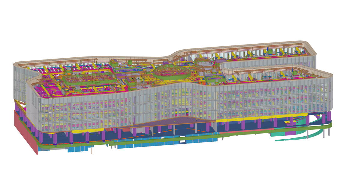
The modeling followed industry guidelines BEC2012 and YTV2012/Talo2000 with precision levels 3 and 4. All design parties operated in a 3D environment, and the plans were coordinated based on models under the direction of the information model coordinator and the lead designer. In addition to the different design parties, suppliers of wood and steel structures, shared mounting solutions, facades, weather protection, and the parking robot were also modeled. The modeling was exceptionally detailed: for example, surface materials and facade elements were modeled at the detail level. The detailed models were widely used in procurement, such as in offers based on the structural modeling of the wooden frame. In all procurements, contractors were also given access to the project's information models.
As much of the structural design material as possible was produced from the model
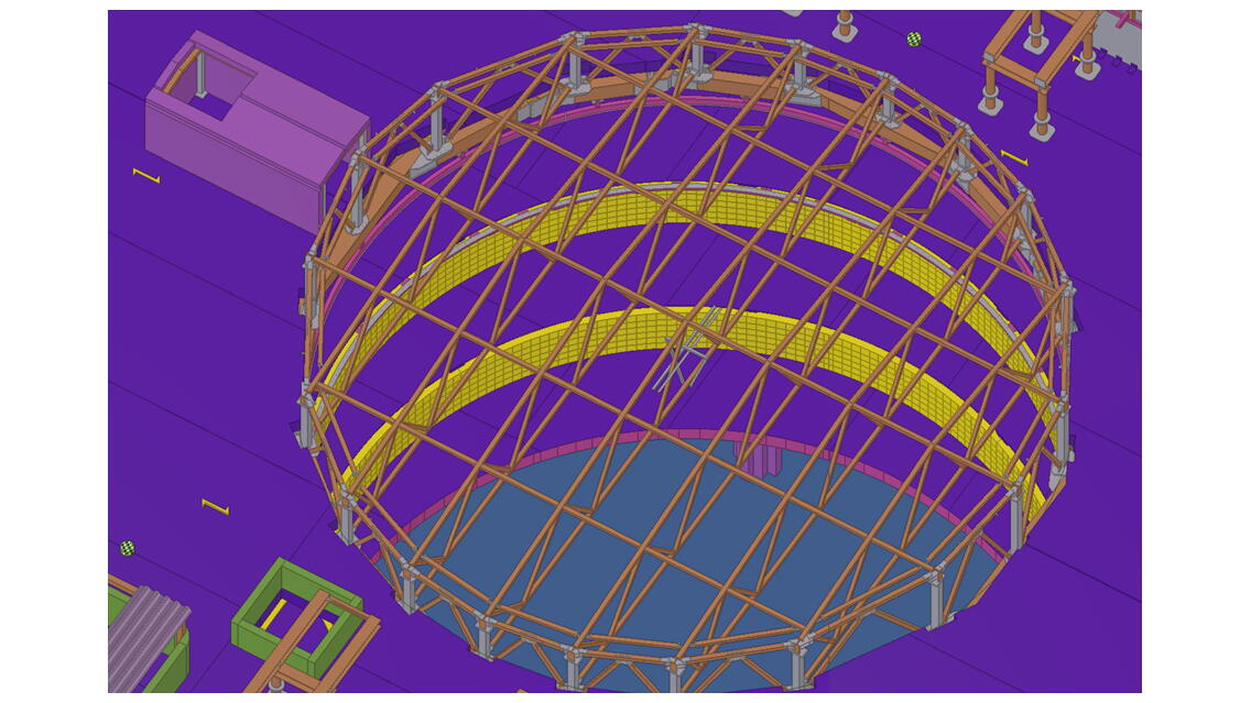
The architectural and interior design was heavily based on advanced modeling. The structural model contains a total of 20,988 assemblies, including 2,482 detailed wooden elements for production. The same structural model was used to design wood and concrete structures and to detail steel structures. The wooden elements were converted into a machine-readable production model directly based on IFC. No part drawings were produced for them. The task of pre-assembling the steel connection parts into the wooden elements was left to humans, and assembly diagrams for the wood-steel assemblies were produced for this purpose.
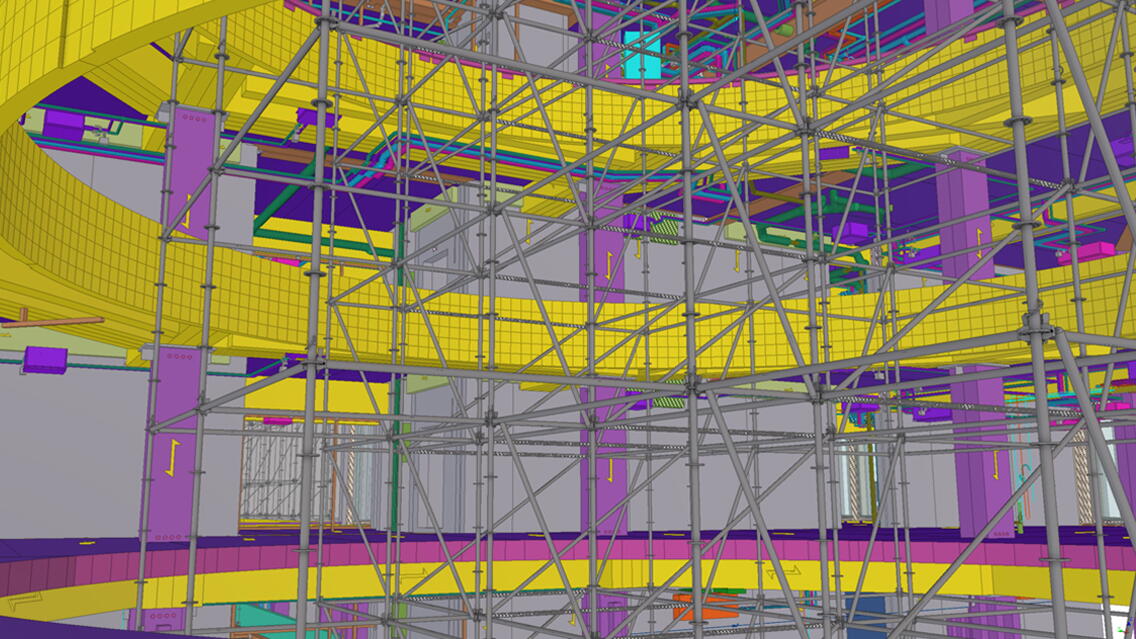
The erection of the frames was simulated during the design phase, and support plans were incorporated into the structural model for this purpose. Due to the two-story high wall elements and the building's geometry, erecting and supporting the frame before the final fixings was challenging, so the installation of each element was phased into a 4D model.
Observations produced from the building information model assisted in planning the communication and architectural design
The detailed building information model produced in Archicad was utilized to enhance the coordination of plans and the resolution of complex, multidisciplinary design entities. Coordination was carried out using Solibri. A key tool in this was the cloud-based BimCollab, which enabled design disciplines to communicate with each other based on the building information model in their native software. The combined model was continuously updated as the project progressed to the construction phase.
The accuracy and coordination of the architectural and interior design were supported by importing the accurately modeled IFC models from other designers directly into Archicad, where the latest models were immediately available to the designers. In all stages of architectural and interior design, Enscape was also used, where game models and visualizations produced directly from the information model served as both a natural tool for communication between parties and an effective tool for the architectural design of the building.
Due to the frame solution, approximately 2,500 MEP penetrations were designed for the building, and Tekla Structures' Hole Reservation Manager was used for their coordination. Collaboration with other product part suppliers also proceeded based on the model: initial data was delivered as IFC, and plans were checked from the model.
Building information models were utilized extensively, including schedule management
Project visualization, plan coordination, work execution planning, quantity calculation for various needs, scheduling, installations, and work supervision were strongly based on building information models. All implementation materials were shared with project parties through the project bank and shared models, and also on mobile devices using the Dalux application, which nearly 150 users utilized on the construction site. Building information models and floor plans were linked to each other, which promoted communication between parties. Building information models supported daily discussions in the site office coffee room throughout the project. For example, the manufacturing status of concrete elements and the status information of the design were updated in the Tekla model to support the site and production.
In schedule management, building information models were utilized in many ways. The challenging earthworks and frame phases were planned and monitored closely using 4D schedules. A schedule, including individual wood elements and installation supports, created together with the contractor, helped identify challenging and even redesign-requiring points in advance. The schedule was planned with the precision of an individual element and its required installation time. Using the 4D schedule, the installation sequence could be planned to be safe and feasible. The installation times and element IDs obtained from it guided factory production and deliveries to the site. The challenging frame phase was completed only two days behind the planned schedule.
The interior phases were executed with takt production, where two separate takt trains moved through the office and hotel rooms on a one-day takt time. Material flows were planned according to the takt and delivered just in time to the takt areas. Material quantity calculations were carried out based on the information model to serve the takt areas. Material delivery data was entered into the material management system, through which deliveries to the takt areas were managed. The site was regularly photographed during construction using drones, 360 cameras, and a fixed camera. The photo material was utilized for communication, work coordination, work monitoring, and mass calculations.
Modeling algorithms were utilized, and wooden elements were modeled for production in the project
The project and, for example, spatial solutions were widely visualized for future users using information models and virtual models based on them to provide a realistic picture well before construction.
The demanding modeling was planned and supervised by Sweco’s “computational designer.” In the project, modeling algorithms were especially utilized in the early stage to create conceptual structural models. Rapid model generation and data transfer, along with the direct utilization of geometry in structural calculations, significantly enhanced this design phase. Algorithms were also later used for challenging geometries and modeling that typically require a lot of manual work. For example, the modeling of the facade's wooden columns to the correct angle was automated based on the architect's floor plan.
The modeling method and data content of the wooden elements were carefully planned at the beginning of the element design, as the modeling of wooden structures in Tekla Structures is continuously evolving. The machine readability of the geometry in production was a basic requirement for the modeling. In addition, the terms and other attributes used for geometry were separately agreed upon with production and implemented in the IFC settings and lists. Surface qualities, load direction, and production direction of the parts were agreed to be represented in the model with separately added components.
To handle the large amount of geometric data of the wooden elements, the modeling method was developed to serve production. Not all process shapes, i.e., shapes cut from wooden panels, were modeled as actual surface geometries in Tekla parts but were represented as separate objects. This enabled more efficient machine readability of the final geometry in production.
The building's goal of low carbon emissions is based on the extensive use of wood, energy efficiency, and renewable energy production. The project's design principles also included a long lifespan and adaptability of use. A hundred-year lifespan for a wooden building also means long-term carbon storage. Models were utilized in the assessment of the project's life cycle impacts during the project and after the design was completed. In calculating the carbon footprint of the building services, the Rava Pro3 TATE naming system was piloted. The project aims to achieve LEED certification.
Project Stakeholder Roles:
Client, developer: Varma Mutual Pension Insurance Company
Architecture and principal design: Anttinen Oiva Architects Ltd.
Main contractor, project management: Haahtela Construction Management Ltd. Structural design, wooden and concrete element design: Sweco Finland Ltd.
HVAC, electrical, and sprinkler design: Granlund Ltd.
Wood material supplier: Stora Enso Ltd.
BIM coordinator: Fimpec Ltd.
Robot parking supplier: Parkstory GmbH
Steel part supplier: VMT Steel Ltd.
Shared mounting rails and maintenance levels: Hilti (Finland) Ltd.
Facade supplier: Haka pks Ltd.
Weather protection supplier: Telinekataja Ltd.
Concrete element supplier: Santalan Betoni Ltd.
Wooden frame assembly: Puurakentajat Rakennus Ltd

