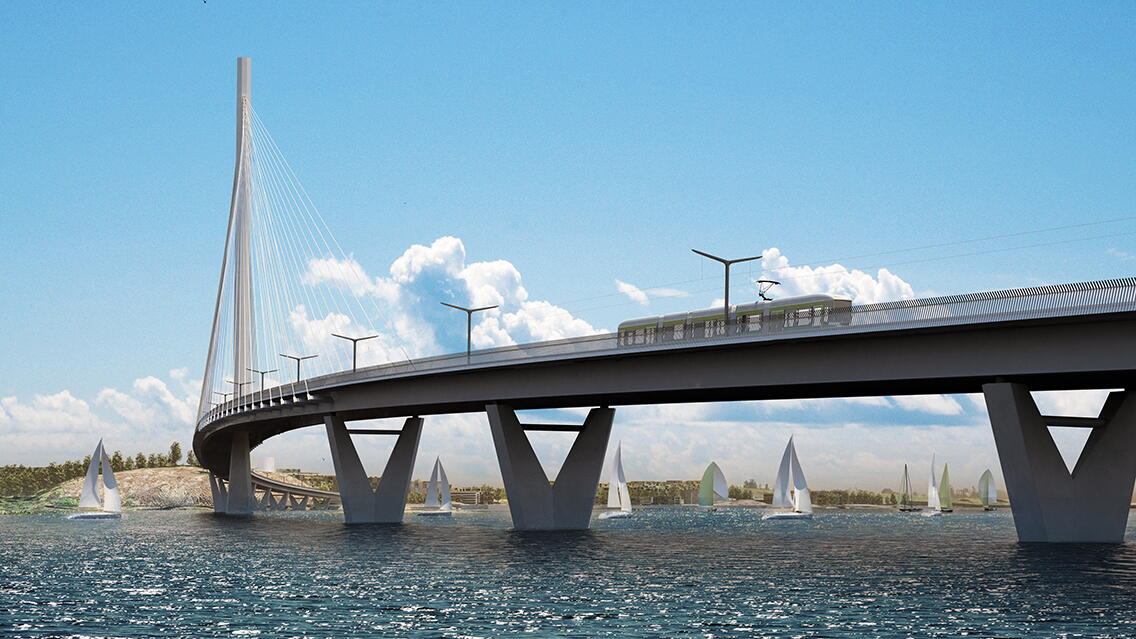
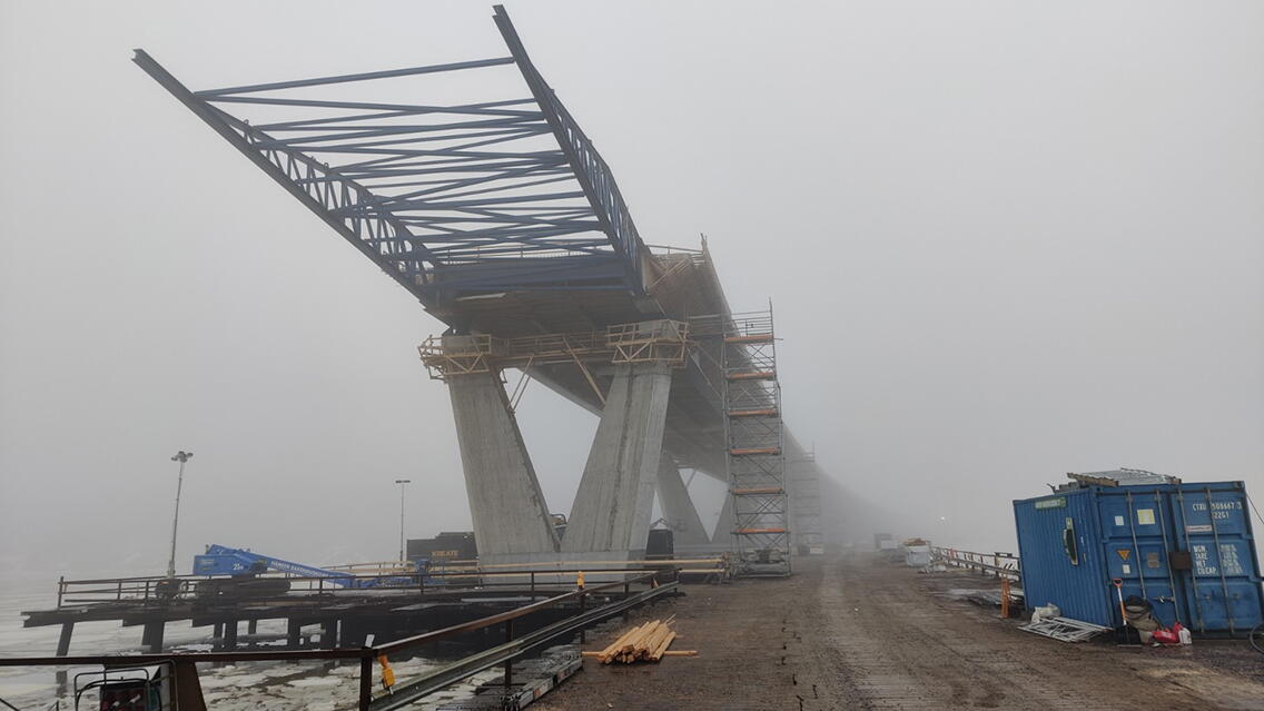
The Kruunuvuori Bridge project will connect the districts of Laajasalo, Korkeasaari, and Kalasatama to Hakaniemi in 2027. At the same time, a new maritime route for tram traffic, cyclists, and pedestrians will be created. The project's goal is to provide the growing Laajasalo with a smooth and reliable public transport connection to the city center.
The Kruunuvuori Bridge is a unique bridge for tram and light traffic. Upon completion, it will be Finland's longest bridge, nearly 1,2 kilometers long, and the world's largest bridge, excluding car traffic. Structurally very significant, the cable-stayed bridge's substructures will be constructed as in-situ concrete deep underwater and the pylon will reach high (+135 m). The steel superstructure will be installed using launching and massive marine lift installations. The maritime environment presents very challenging conditions for construction.
The project, commissioned by the City of Helsinki's Urban Environment Division, began with an international design competition in 2011. The competition was won by a team led by WSP Finland Oy in collaboration with Knight Architects Ltd. The general construction, implementation, and detailed design of the bridge were carried out by WSP Finland Oy from 2012 to 2020. The Kruunusillat consortium formed by Kreate and YIT as general contractor won the bid for construction. Construction began in 2021, and the workshop and implementation design of the bridge's load-bearing steel structure were carried out by Ramboll Finland Oy in strong cooperation with the Kruunusillat consortium. The structures will be completed in 2025, and the bridge will be taken into use in 2027.
Street, road construction, and bridge and engineering structure design using BIM
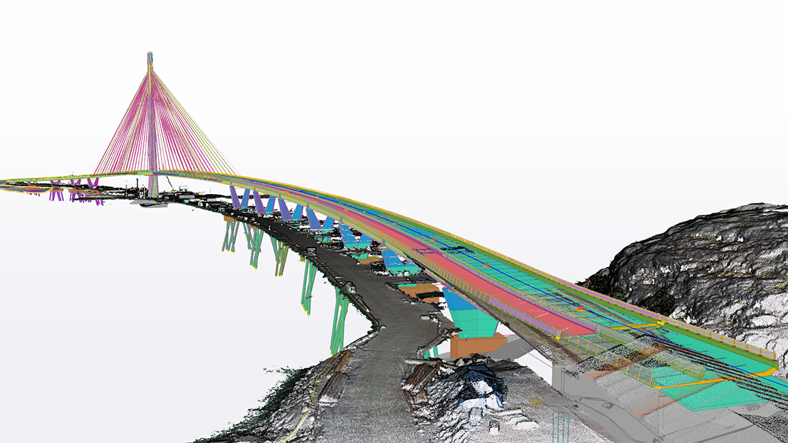
The client utilized modeling to support decision-making by providing easily understandable visualized information for decision-makers and preliminary cost analyses of the project's expenses. The openly displayed presentation model also served as a visualization of the project for city residents and decision-makers. During the construction planning phase, the building information model was used to integrate the design fields and fit the project into the urban environment. The model-based material was also shared with contractors during market dialogue and tender phases. During the construction phase, the general contractor does quality assurance reporting, the completion status and the billability of installments using the collected as-built model.
Bridge Information Modeling (BrIM) has been integrated into the project from the beginning as a key part of the overall strategy, requiring the modeling of all plans, including temporary structures and manufacturing drawings. Contractors' project management and quality systems are tied to the data associated with these models. The abundant data serves as a foundation for a real-time situational awareness system that combines orthoimages, 360-degree images, and up-to-date plans. The result is an advanced system for real-time schedule tracking and monitoring of safety and quality measures. The situational awareness requirement is an additional requirement for up-to-date as-built models. Comprehensive BrIM integration via Trimble Connect streamlines the construction process and ensures the project's accuracy, efficiency, and transparency to all parties.
Building information model as a continuous part of the design process
Technical disciplines were coordinated in a combined model using Navisworks. Based on the model, quantity estimation was carried out. Design meetings discussed solutions by viewing the building information model.
From the very beginning, the project has been a building information model project. The client's goal was to construct the bridge entirely based on the model, practically without drawings. The drawings produced for the project were made lighter and only for archival purposes and to aid in interpreting the building information model. For example, the drawings did not show steel positions at all, and only principal cross-sections were presented for reinforcements.
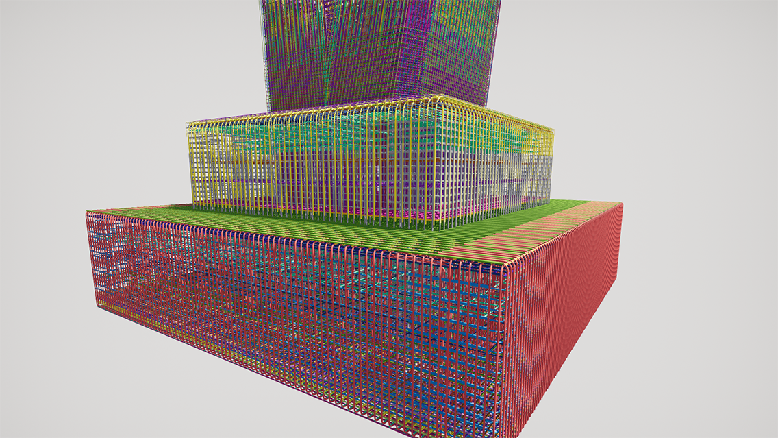
All designs of technical disciplines were based on the model. Structures were modeled using Tekla Structures. The main tools for related infrastructure and environmental design were Novapoint and Autodesk Civil 3D software. In addition to the main systems, numerous other software supporting model-based designs were used.
Technical disciplines collaborated based on the model. At the start of the project, there were few practices and processes, and collaboration was tested on various platforms. Trimble Connect later proved to be the best. The project also used an augmented reality application, which allowed viewing the bridge in its real environment during the early design phase.
Seeking new tools for parametric modeling due to project complexity
The project's size and geometric complexity drove the search for new, more efficient parametric modeling tools. WSP had experience with small-scale use of Grasshopper in previous projects, but in 2017, Kruunuvuori Bridge became one of the first bridge projects in the world to use Grasshopper for the entire bridge modeling. The same parametric geometry defined in Grasshopper was used for creating both the Tekla model and calculation models in SOFiSTiK software. This was a completely new design method that has since become more common in bridge design.
Parametric information modeling allows for rapid changes to the building information model, even during construction. An example of this is the entire deck reinforcement of the bridge, where the locations of splice lengths and the construction principle were changed after construction had already begun. The deck reinforcement was defined parametrically in Grasshopper, allowing changes to be modified at once for the entire length of the bridge. Since the bridge is very long, there are also a significant number of reinforcement bars and splice locations. Modifying this with traditional Tekla modeling would be a very long process. Even over five years later, the algorithm worked excellently, and the change was made efficiently.
Utilizing modeling software for the virtual model of the project area
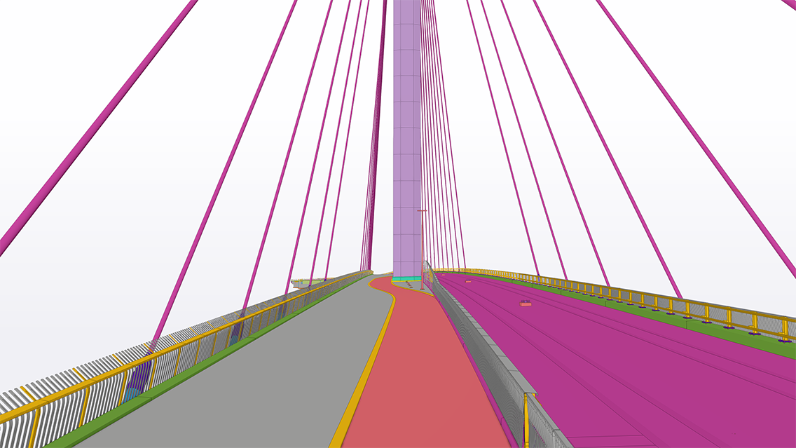
Material produced with Tekla Structures and other modeling software was utilized in a virtual model of the project area created with the Unity game engine. A single model added value to architecture, street, environment, traffic, guidance, and lighting design, as well as administrative and general communication and other interactions. In addition to understanding spatial and landscape visual impacts, the model added special value in simulating the impacts of scenarios and design options.
Through the virtual model, the placement of light sources and types of lighting were optimized, and the functionality of adaptive lighting was examined. Observations made using the model led to the development of lighting optics integrated into the outer railing as a standard lighting product in collaboration with a lighting manufacturer. Model-based simulations examined the design and structure of the railing in conjunction with wind studies to achieve a wind-breaking and mitigating solution. The virtual model also allowed for the examination of traffic situations and user experiences from both tram and light traffic perspectives. The results were utilized in the bridge's furniture and railing design.
In wind technology analyses, building information models, 3D printing, and CNC milling were used to construct wind tunnel models. Two full-scale models of the entire bridge and a cross-sectional model of the deck were created and tested in the wind tunnel. These examined structural questions and the impact of wind protection railings. The wind tunnel test program is the largest implemented for a bridge in Finland.
Project stakeholders were committed to model-based work through intensive early-stage involvement and the creation of a jointly beneficial practice. All model-based activities were maintained in a Trimble Connect project hosted by the contractor. Information from other systems was linked and brought into it, so almost all material produced in the project was accessible via the building information model. Compliance material was checked using the as-built model.
Assembly and part drawings directly from the Tekla model
Within Ramboll, BIM technology was primarily applied to factory production and detailed design of steel structures. The process produced all necessary manufacturing drawings, including assembly and part drawings, directly from the Tekla model. Additionally, the model facilitated the production of NC and DSTV files for the manufacture of individual parts and was crucial in compiling material lists to obtain accurate steel quantities.
The project, which expanded the creation and automation of drawings, produced over 7,500 documents, reflecting the extensive output of the BrIM model. Certain structure angles were not measured manually or added to the drawings. They were automatically calculated, stored as attributes in the model, and dynamically displayed in the drawings, ensuring an up-to-date and accurate presentation.
A new approach: maximizing model-based erection guidance
The model provided by the client follows the final geometry of the bridge, and the fabrication model created by Ramboll follows the fabrication geometry. During construction, neither of these geometries is physically present on-site.
The traditional method of controlling the structure's geometry during construction involves monitoring the difference between the final geometry and the plan and mapping the relative geometry of the structure using drawings. These illustrate the relationship between the existing structure and the assemblies to be installed. Predetermined points from the plans serve as benchmarks for the surveys.
In constructing the Kruunuvuori Bridge, geometry control was efficiently implemented by creating separate IFC-format geometry models for each key construction phase. The SOFiSTiK model enables intelligent and consistent updates that reflect changes, work implementations, or tolerances as needed. This iterative process ensures that an up-to-date model is available for later construction phases, providing an accurate situational picture of the current state. This dynamic approach also forms the basis for quality assurance, allowing documentation to be adapted to the actual conditions on the construction site. The geometry of the plan is automatically integrated, and all deformations, including plan deviations, rotations, and beam twists, can be accounted for. This was done exclusively in IFC format with IFC-compatible total stations.
The positions of marine cranes were ensured by comparing IFCs of the cranes to sounded seabed model. Utilizing models directly for geometry control removes the limitations of measurement points, allowing any point of the structure to be measured and compared.
Measurement using the IFC model without separate CAD measurement files
The contractor positioned the erected segments solely in IFC format using IFC-compatible total stations. IFC models provided precise segment locations for beam assembly placements. A typical assembly cycle included measuring the structure's geometry after launching. The analysis model (FEM) was adjusted accordingly, taking into account adjustments due to the installed structure and effects such as twisting caused by the diagonal brace. This ensured that the new segment was seamlessly integrated into the existing structure. The subsequent assembly geometry, covering both the already constructed part and the new segment, was provided in IFC format. Typically, new segments were delivered to the site the next day, ensuring a quick and efficient workflow for all parties involved. This approach provided a comprehensive visual representation of the situation and required actions, promoting communication and quality while significantly reducing the likelihood of human errors. It proved to be the fastest, easiest, and most straightforward way to produce and share information.
Identification of the most stressed structural components as a significant part of the design
The design service life of the bridge was exceptionally long, with the load-bearing structures expected to last 200 years. A significant part of the design involved identifying the structures and structural components subject to the highest stress and that are irreplaceable. The long service life particularly challenges the design of the bridge's load-bearing structures, namely the steel and concrete structures. The highest stress is exerted on the concrete structures in the water's fluctuation zone. Part of the design work included defining the concrete product requirements to match the project's demands, thereby extending the service life of infrastructure concrete.
The durability of the bridge's steel structures is ensured through careful design and implementation to avoid potential fatigue in the steel structures. Fatigue in steel structures is particularly evident in long-term use, especially in joints and stiffeners, so the design focuses on finding the simplest and most functional solutions possible. Seasonal and weather variations were also considered in the design of the cable-stayed bridge's steel cables. The potential accumulation of snow and ice on the cables during winter is addressed with structural solutions that prevent ice formation and through proper maintenance.
The bridge is located in a maritime conservation area and is part of the view of several valuable cultural environments, including the UNESCO World Heritage Site Suomenlinna with its water areas, as well as the public parks of Mustikkamaa and Korkeasaari, and the maritime villa areas of Kruunuvuori. The Unity game model was used to study lighting solutions in this sensitive area. The lighting must be as subdued as possible yet safe, and light pollution must be minimized. There are three different types of lighting solutions.
The model also examined the design of railings. The structure and design of the railing were done in conjunction with wind studies, as the railing must break and mitigate the wind. In the model, a tram ride was simulated with views towards the sea to the north and south, comparing the use of designs and colors. By fully utilizing WSP's wind engineering expert's special expertise, design changes could be analyzed without delays and additional tests. The analyses accurately determined wind-related vibration limits and risks, resulting in the bridge being implemented without aerodynamic structural changes. Realistic values for dynamic wind loads were determined, avoiding material waste and environmental impacts associated with over-dimensioning.
An as-built model of the bridge will be created, which will serve as a maintenance model and act as a digital twin of the constructed bridge.
Project stakeholder roles:
Client: City of Helsinki/Urban Environment Division (KYMP
Lead Designer, General and Detailed Design 2012-2020 (including bridge, traffic, and street design, lighting and electrical design, wind and geotechnical engineering, water supply and technical networks design, street environment design, and structural design of related areas) and Client's Expert: WSP Finland Oy
Main Contractor: Joint venture of Kreate Oy and YIT Infra Oy, Kruunusillat
Contractor's Designer (fabrication and execution design of the bridge's load-bearing steel structure): Ramboll Finland Oy
Winner of the International Bridge Competition 2013 Gemma Regalis: Knight Architects & WSP Finland Oy
Superstructure and Pylon Geometry Management: SOFiN Consulting
Steel Structure Supplier, including fabrication and installation as well as design of installation structures: Nordec
Client's Representative for Site Supervision: HTJ
Responsible BIM Coordinator for the Contract: TYL Kruunusillat

