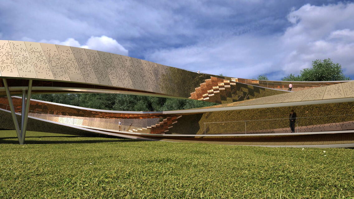
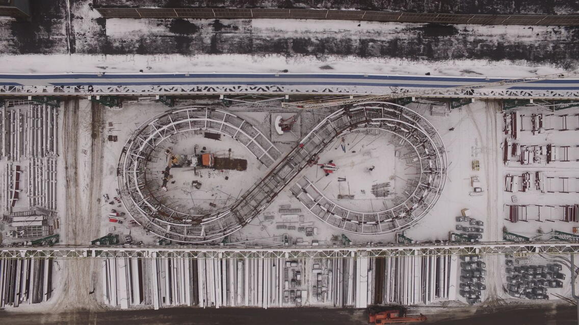
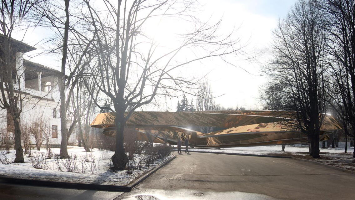
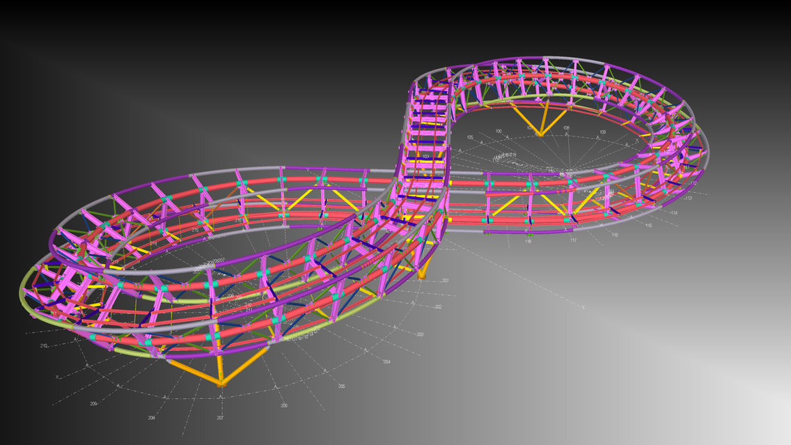
Continuous walking route that stretches along the supporting structure in the form of an infinity symbol
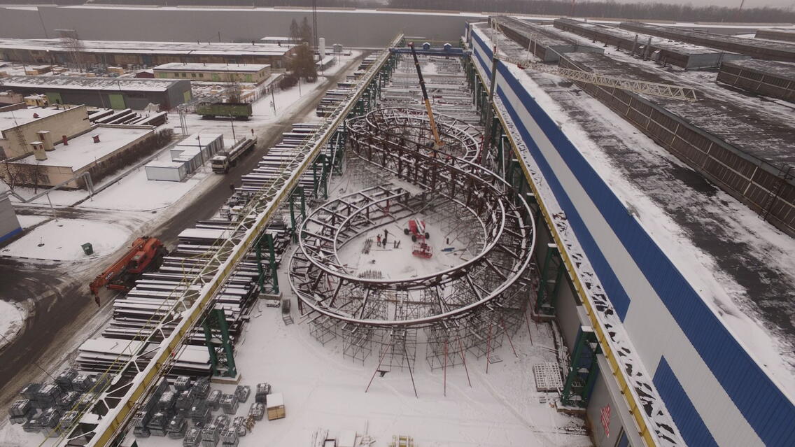
The Mobius strip will be located in the area of the Cultivated Nature landscape park at VDNH in Moscow.
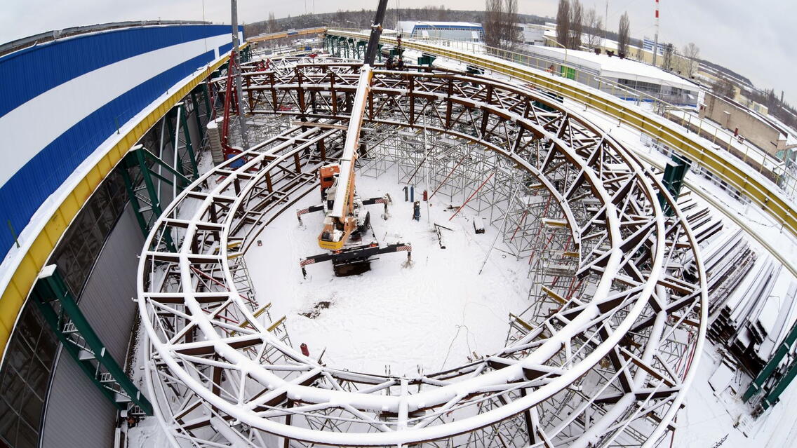
The length of the route is about 300 meters, and the height of the structure is 8 meters. The landscape attraction is created as a continuous walking route that stretches along the supporting structure in the form of an infinity symbol. The “Mobius Strip” will surround the garden of five senses (sight, hearing, smell, touch and taste). The 3D model and drawings in Tekla were completed in 2 months. The manufacture of metal structures with a general assembly in the territory of Belenergomash took 3 months.
The roles of Belenergomash-BZEM, LLC in the project were design development, steel structures manufacture, general assembly and installation organization.
Project Features
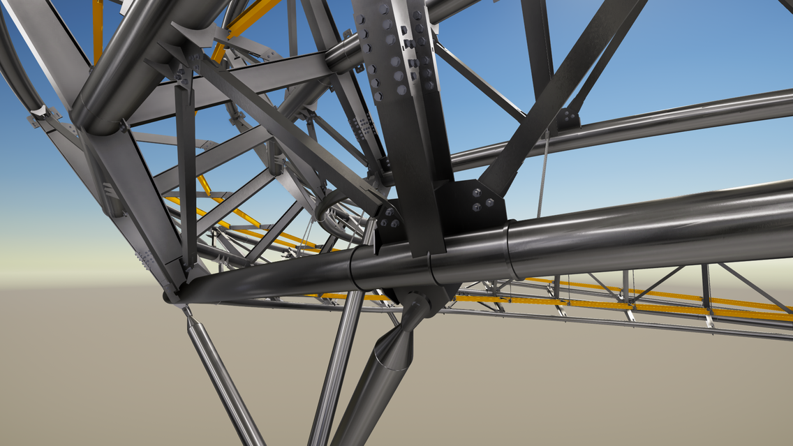
Structural stability is ensured by a rational solution of the system of transverse frames and contour beams with rigid connection nodes, which increase the degrees of static indeterminacy and ensure the spatial work of the structure.
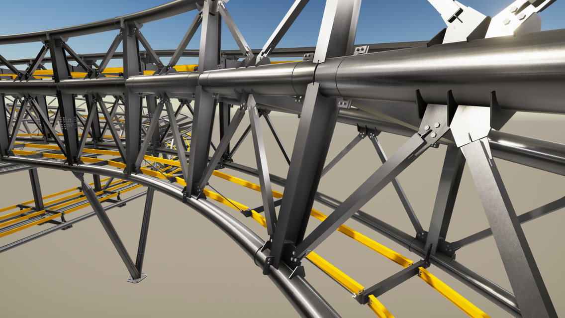
Geometry
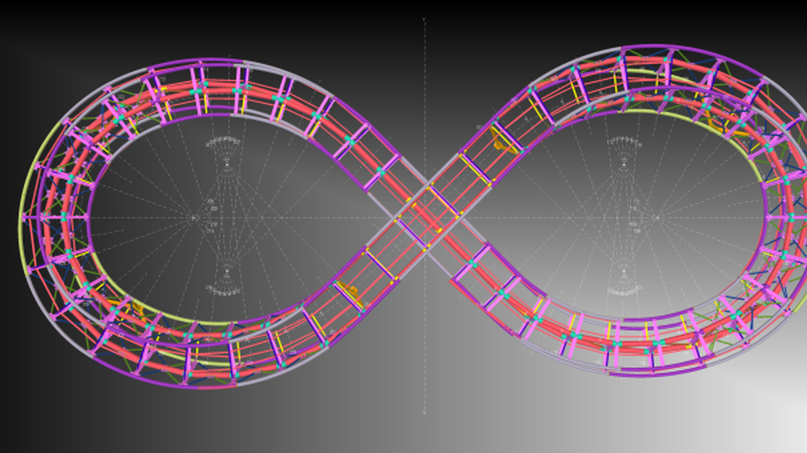
The tape is a closed structure of complex shape with a dimension of 65.7x26.5 meters, skew-symmetric with respect to the central axes. The cross section of the tape is an I-beam, smoothly changing the height, and turning relative to its own axis. The dimensions and height of the structure were selected in such a way that a passage along two transition bridges with a size of 1400x2100 mm is provided.
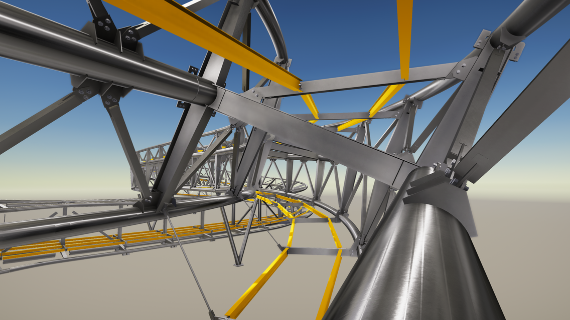
Structural description
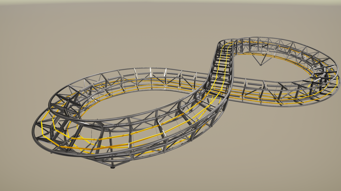
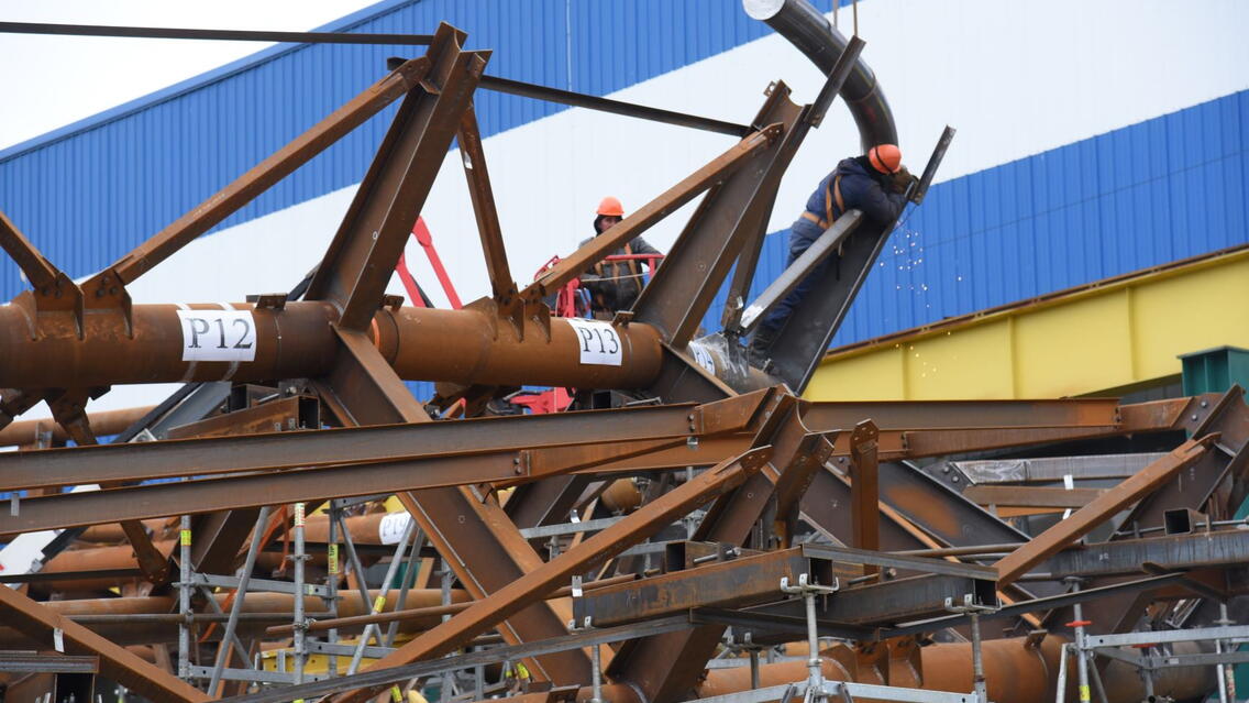
The bearing structures of the tape are a spatial structure consisting of 46 transverse H-shaped frames of welded I-beams of variable and constant height. Frames are united in a single design by contour beams of round pipes, as well as a system of ties from square pipes. The tape rests rigidly on reinforced concrete structures through 2-3 columns of round pipes rigidly pinched into the foundations.
What were the challenges and what made the project successful?
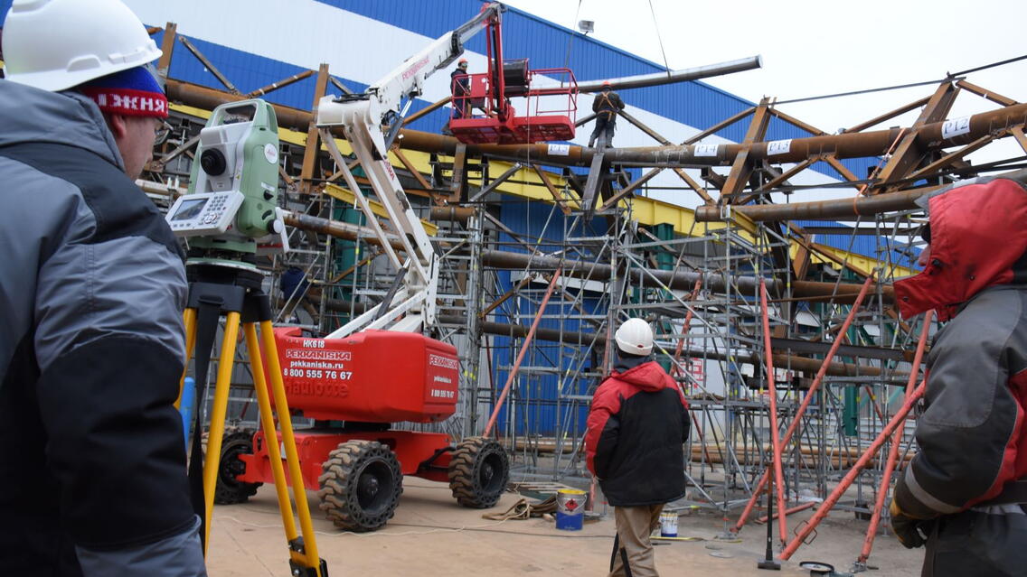
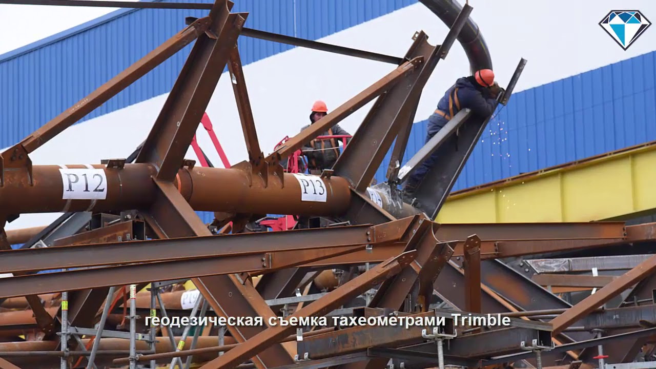
- Geodetic survey was used with Trimble tachometers during the construction
- Own development and use of standard plug-ins for pipes for the correct unloading of CNC on an HGG machine
- Ensured bent rolled tubes convergence due to precise control and point coordinates uploaded from Tekla Structures model
- During the general assembly the specialists were convinced that the utilized technologies allow erect steel structures of such complex spatial geometry.
- Interaction with designers
- From the design organization, the frame geometry was obtained from the calculation model in IFC format
For control, the export / import of point coordinates was used to check the manufactured complex assemblies. On such complex projects, the entire team of production technologists works with a detailed Tekla Structures model.
During the general assembly, the constructors were given a model in IFC, Web Model XML and 3D DWG formats. Model preview was available within Tekla BIMSight (ed. Trimble Connect). All project participants agreed on the IFC format as the main format for data exchange.
Tekla Structures in the workshop
For complex assemblies, the technologists used the model and prepared a sequence of actions for the assembler to help the CMD drawings.
The project in numbers
- LOD 500
- Steel –161 tonnes
- Project team – 12 people
- Bolts – 2611
- Details – 10,000
- Drawings – 1773
- Project duration – 2 months