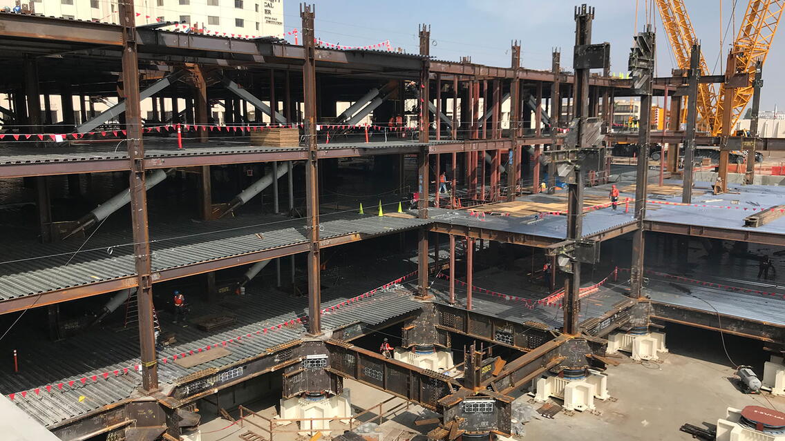
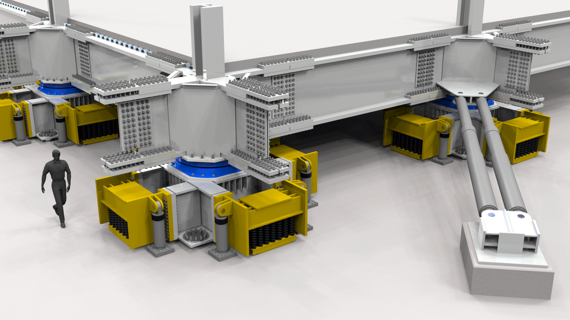
The Loma Linda hospital is an 18-story hospital made up of 6 main podium levels before the building splits into two towers, a 10-story Children’s hospital and an 18-story Adult’s hospital. This new structure is an extension to an existing hospital which has been built in the seismic active area. Due to the seismic activity, the building incorporates a number of seismic resistant design concepts such as sideplate technology and buckling-restrained braces as well as an extremely complex base level that has a grand total of zero traditional anchor/holding down bolts to the foundation.
The image on the top right is of the base level and consists of (from the foundation up):
1. Steel plated pedestals. These pedestals do not directly fix to the foundations. There are four pins, one in each corner, the pins range from 6” to 12” in diameter, and are guided by post grouted sleeves that contain Nyloil guide bushings. In addition to the pins, there are seismic spring mounts (shaded yellow in the image) bolted to each side of the pedestals.
2. Secured to the top of the steel pedestals are triple pendulum bearing isolators (shaded blue in the image). These bearings provide approximately 3’-6” of movement in all directions.
3. Fixing atop of the bearings is the first level of steel framing which consists of 60” deep plate girders with flange material up to 4” thick and web material up to 3 ½” thick. Typically, the plate girders are spliced together with bolted splice plates; however, there are a few splices that require field welding. Where the plate girders intersect, a plated box section filled with concrete houses the building column profiles which extend through to the base of the plate girders.
4. Finally, to complete the seismic design there are fluid viscous damper braces which fix the plate girders back to the foundations via an embedded plate bracket.
The project consisted of approx. 21,500 tons of steel.
The base level plate girders required 42,000 1 ¼”ø bolts in the plate girder splices alone.
BIM Coordination aspects;
• Structural support framing for imagining equipment pads which were set in concrete.
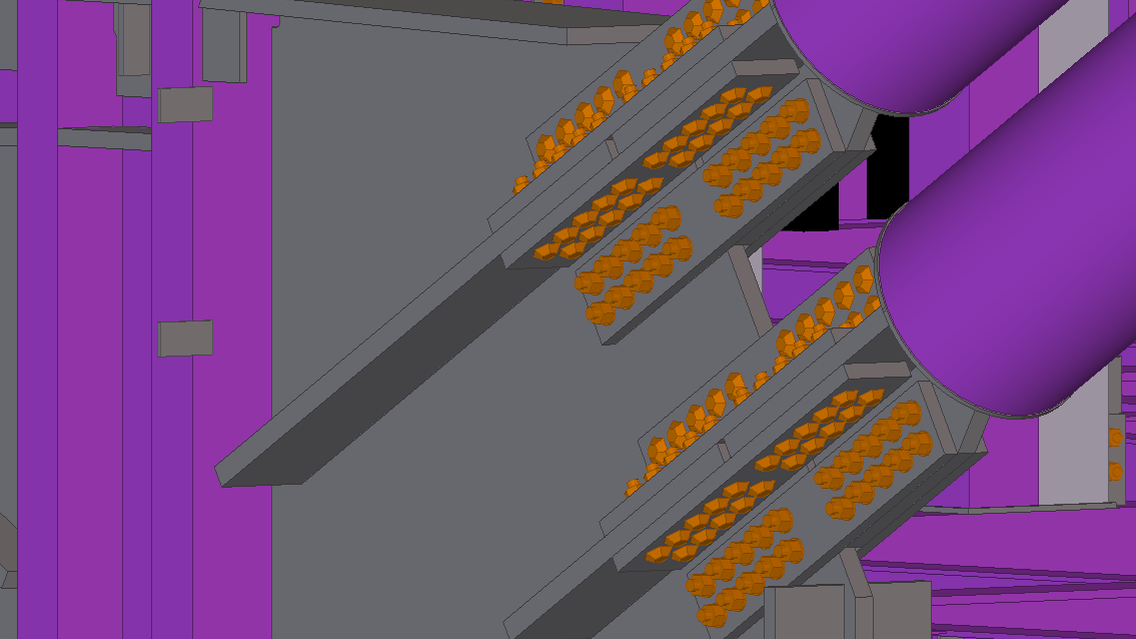
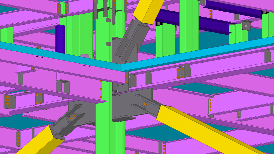
• Modelling of “Protected zones” for both the BRB bracing and sideplate seismic system which was required for trace coordination and fabrication.
• Positioning of MEQ (mechanical equipment) support beams.
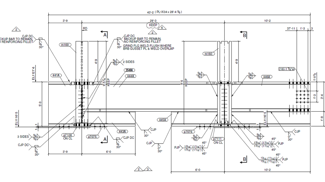
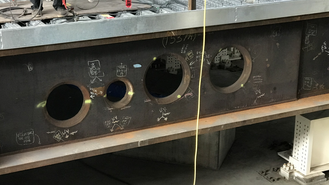
• MEP support beams and penetrations (see last image on the right, beam penetrations at the base level).
• Electronic model review of early sequences to support the aggressive construction schedule
