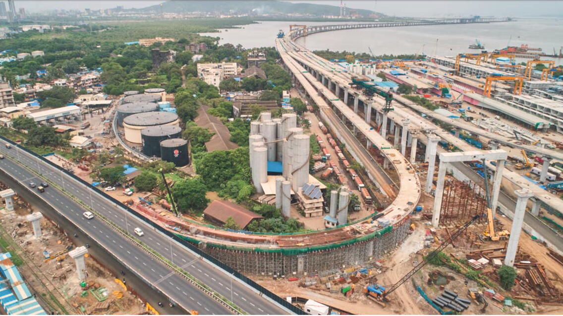
Mumbai Metropolitan Region Development Authority’s (MMRDA’s) Mumbai Trans Harbour Link (MTHL) is a 6-lane road bridge across the Mumbai bay between Sewri in Mumbai and Chirle in Navi Mumbai. At 22kms, it is the longest sea link bridge in India.
- Package-1 covers 10.38 km which is broadly divided into 3 zones viz., marine zone which is about 5.755 km, intertidal zone which is about 4.130 km and land zone (Sewri interchange).
- In the land zone, there are 8 ramps that connect the MTHL main bridge with the existing Eastern Freeway (4 ramps), the proposed Sewri-Worli elevated bridge (2 ramps), and MBPT road below Eastern Freeway (2 ramps).
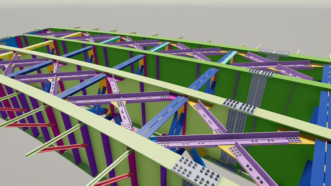
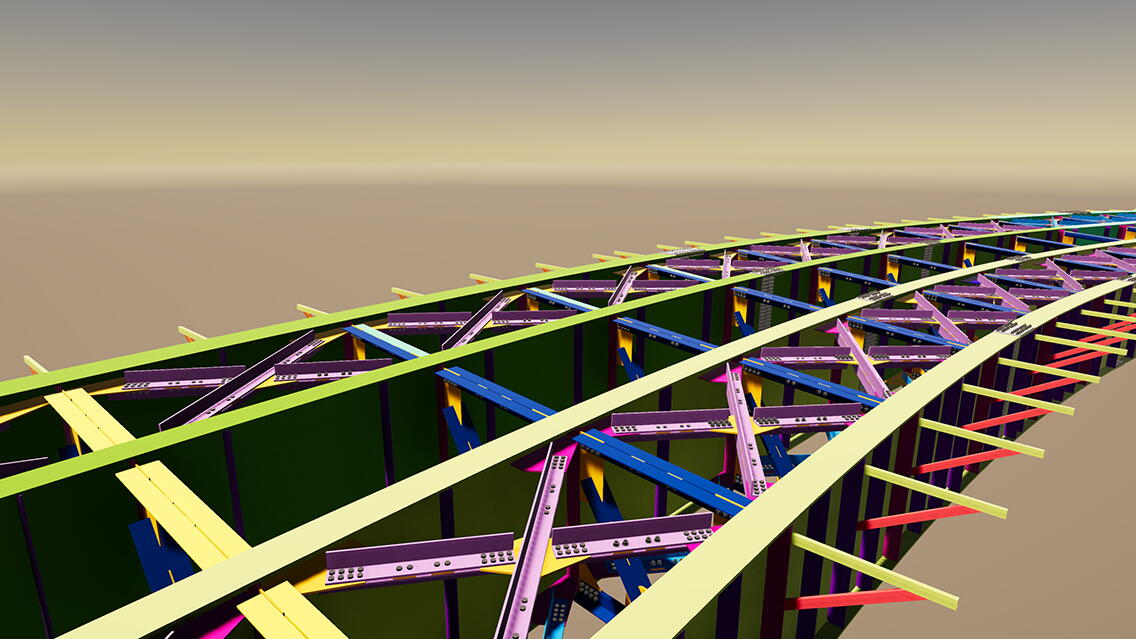
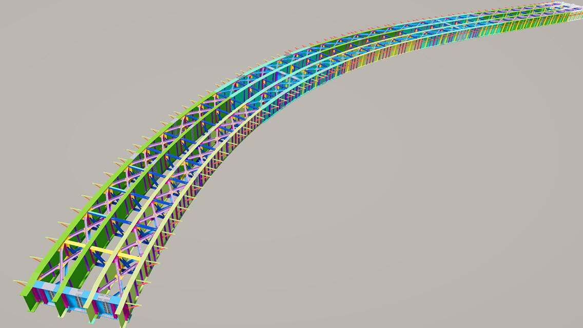
- At interchange location, ramp-A & ramp-B was built using composite steel girder with compounded curvature. Below are the ramp details,
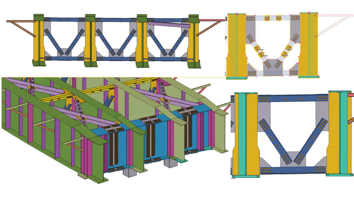
- Ramp-A: Overall length 80m with 2 spans each of 40m length and having radius 304m and comprised of 4 deep girders with cross girders at diaphragm and vertical, and plan brace having overall weight of 250 MT.
- Ramp-B: Overall length 120m with 3 spans each 40m length and having double radius 300m/75m and comprised of 2m deep dirders with cross girders at diaphragm and vertical, and plan brace having over all weight of 400 MT.
Challenges
- The main challenges faced were during modelling of the built-up girder and formation of the girder for compounded curve, pre-camber value, superelevation, and road gradient.
- Formation of bend gusset for connecting the plan bracing with the differential level of deep girders.
- Difficulty in extracting the NC & DXF file for curved girder plate and bend gusset.
- Girder is built-up section with curvature and conventional commands are not applicable on it. In addition, girder has pre camber values at every 3m therefore it has multi points in single segment.
Benefits of Using BIM & Tekla Software
- By implementing Tekla Structures the project team was able to model such complex geometry with pre camber at every 3m interval with smooth curve & prescribed radius.
- At the stipulated time the detailing work was completed, and the team achieved the major milestone of the project.
- BIM implementation made fabrication of such complex girder much easier. In addition, it forecasted difficulties at the detailing stage. Since conventional commands are not applicable on girders, the project team received guidance from the Trimble technical support team for modelling and used the latest inventory Bridge Creator tool of Tekla Structures for formation of girders.
- Girders have pre camber values at every 3m and multi points in single segment. The advanced tool surface generation enabled the team to make multi points in a single built-up girder.

