The largest machine in Europe to produce liquid paperboard packaging
Swedish forestry company BillerudKorsnäs decided to invest in a new KM7 paperboard machine on its plant in Gruvön in December 2016. The value of the investment is 5.7 billion SEK, and the new machine is to start production during the first quarter of 2019. The largest paperboard machine in Europe will produce material for liquid packaging.
The Next Generation project kicked off with pre-planning in 2015, and implementation planning started immediately after the investment decision in December 2016. Pöyry’s services for the project include all the design disciplines for the machine building, pulp mill and tower area, including process, plant, mechanical and structural engineering as well as steel, CIP and precast concrete design. The project was the largest forestry project for Pöyry in 2017. The company was responsible for BIM coordination among the design disciplines and sub-consultants.
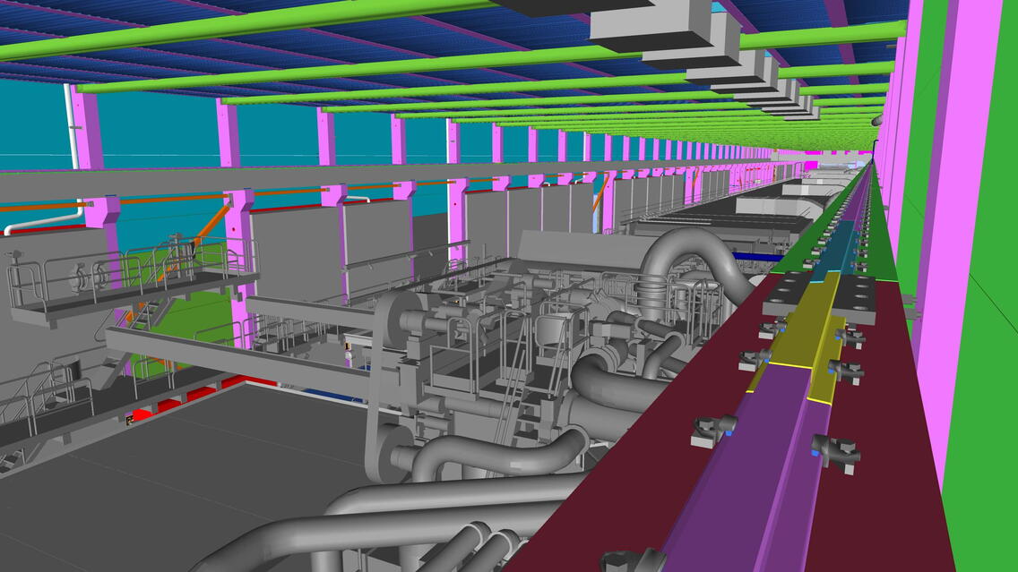
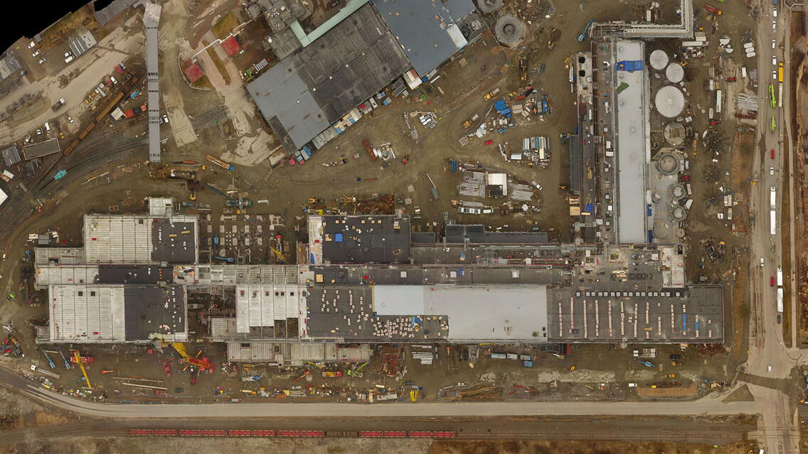
This exceptionally large project required new ways of modeling to be developed and utilized. The machine room of about 450 meters was a large complex to work on. Due to the fast schedule, several designers needed to design and detail certain areas simultaneously. Altogether 118 professionals from Pöyry and 35 sub-consultants worked on the structural design of the 74,706 m2 space. The project lays on circa 125 km of piles. It uses 10,800 precast concrete units (ca. 80,000 tons of concrete). The weight of the largest column is 76.2 tons, and its length is 27.2 meters. All 225 columns have been individually transported from Iisalmi, Finland, to Gruvön, Sweden, which makes about 1,157 km in total. There are 2,235 precast concrete wall units that have been manufactured in Finland, Estonia and Latvia. Measured by truck loads, the delivery forms a line that is 75 km long.
All design disciplines committed to a model-based process
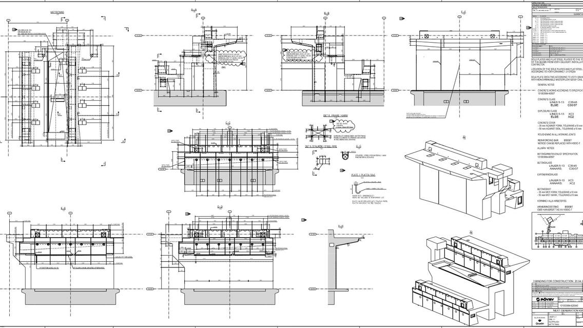
All precast concrete design including frame, slab and wall units was performed with the help of Tekla Structures. All reinforcements were modeled and drawings produced from Tekla. BIM enabled to avoid design errors, which automatically reduced the number of RFIs. Best modeling practices ensured that the precast elements were manufactured efficiently, and they cloned exceptionally well. Thanks to modeling, no faulty precast elements resulted on site, and the precast elements were installed without problems. The 3D model used on site helped illustrate the structures. There are fewer clashes, and managing information between various parties is easier and more coordinated.
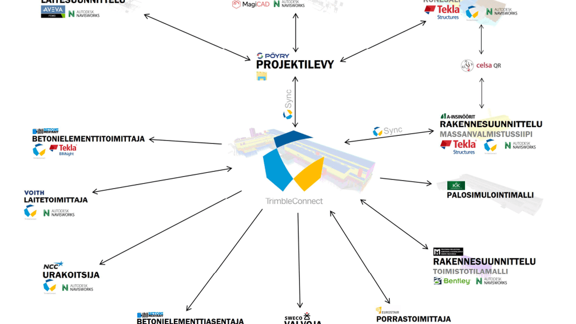
Due to the scope of the structural design, the project used Finnish A-Insinöörit Suunnittelu and Polish H&M as sub-consultants. Therefore, sharing the Tekla models was clearly key in the success of the project. Trimble Connect was used to share the IFC files, enabling automatic transfer via a single channel every night. In this way the sub-consultants always had access to the latest structural models. Sharing the DGN models of other disciplines also worked fine using the Trimble Connect service. In a later phase of the project, this channel proved a practical and easy way to share the model with other stakeholder groups including the contractors.
Reference files were exported and imported between Tekla and PDMS using the Export-to-Aveva tool, and the IFC files were exported using BIM Publisher. Due to the challenging terrain, the construction required massive piling. To manage the pile data, a new way of importing actual pile positions to Tekla Structures was developed during the project. By using the Grasshopper-Tekla live link, the actual positions of the piles were visually coded into the model. Grasshopper was programmed to read accurate positions including gradients and codes directly from an Excel file.
Celsa QR services were used to export reinforcement data from Tekla and to create XML fabrication files. Grid tags were added to combination model to ease the navigation in the model and Trimble Sketchup was used to create these. Since reinforcement data was designed and modeled in the Tekla structural model for the construction site, the data was able to transfer as fluently as possible all the way to the fabricator. The Celsa QR 4 Tekla plugin is able to read reinforcement data from the model and save it in a file format requested by the fabricator in order to enter data directly to the bending machines.
In Sweden, contractors typically want XML files to order and fabricate reinforcements, and the files make delivery considerably faster. Without the XML data, the production is delayed for a couple of days. Ordering reinforcements using traditional text-format lists only stalls production because the measurements and other data need to be entered into the workshop system manually and then reviewed with the designer. Reinforcement supplier Hercules armering’s usual delivery time is 15 days, but for the Next Generation project, they were able to deliver in just 5 days. Delivery times have held true despite a demanding schedule. This is mainly thanks to qualified source data and ready-to-use fabrication files created directly from the Tekla Structures model via the plugin.
In precast element production, the structural models were utilized for various checks including location, length and weight. Since the models were updated every day, they always provided the latest data, also for the precast elements that did not yet have production drawings. By using the models, the manufacturer was able to predict demand and steer production to various factories before delivering the drawings. In addition to production management, BIM helped perceive the big picture and obtain quantity calculations, such as actual number of precast elements, penetrations and reinforcements.
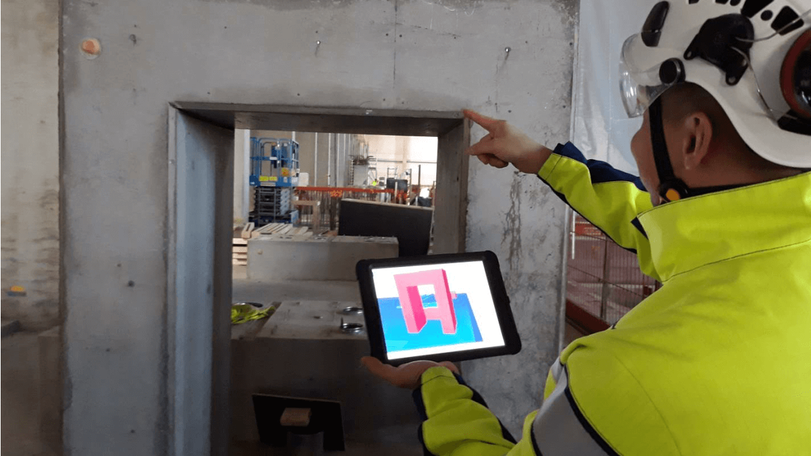
The models were used during installation to locate the correct units based on their codes. Task planning is much easier and more perceptive using the models compared to tables. The models also help plan crane work because they can be used to measure building distance and height. Thereby it is easier to design and visualize the location and reach of a crane. Information exchange between the project parties is more effective using screenshots from the model. In the meetings, the models proved an excellent visual aid to explain installations and their impact to contractors. Detailed models also help illustrate steel structures, connection details and obligatory installation sequences.
Project parties
Process design: Pöyry Finland Oy
Plant design: Pöyry Finland Oy
Structural design and detailing: Pöyry Finland Oy
MEP design: Pöyry Finland Oy
Structural design subconsultant: A-Insinöörit Suunnittelu Oy
Structural design subconsultant: PPKBHM
Technical fire consultant: KK-Palokonsultti Oy
