A record array of software and other tools for digital construction used on the Oasis of Professionals campus
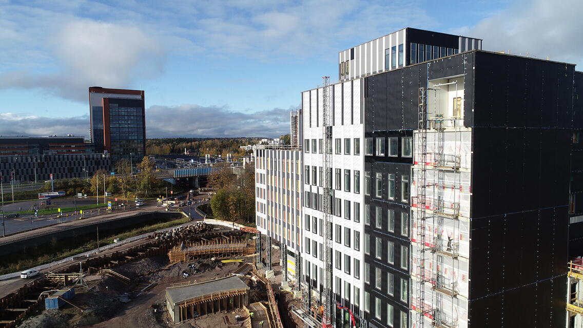
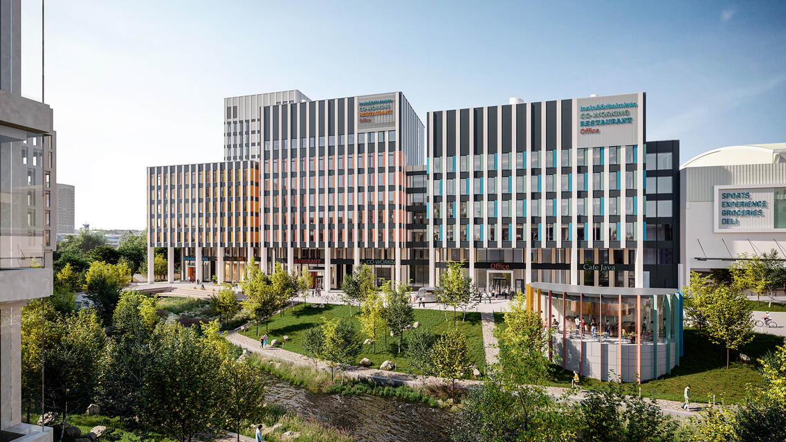
Oasis of Professionals (OOPS) is a new block of buildings developed by NCC in the Leppävaara district of Espoo, in a prominent location at the crossroads of Ring Road I, the coastal railway, and the future Jokeri Light Rail. Eventually five office buildings, a hotel, and residential space covering close to 100,000 m2 in total are built phase by phase in this area of Hatsinanpuisto. The construction began in June 2019, and the first phase includes two 7–13-storey office buildings plus an annexed parking garage, both to be completed in August 2021.
NCC Property Development was the client and NCC Finland the main contractor in this project, the services of which will be used by up to 500,000 persons in the catchment area. Climate change impact is taken into account in the development of the area, and the objective is to obtain a BREEAM Excellent environmental certificate for the office buildings.
Trimble is the anchor tenant of the first-phase office campus, and thereby the project made extensive use of Trimble’s software and tools from project planning to construction. For example, Trimble’s XR10 hard hat was put to use for the first time in Finland on the OOPS site. This project brought on a completely new role at NCC, too, one of the digital engineer, the task of whom is to implement BIM and digital tools on site.
The property’s busy location was a challenge. The plot is bordered by the railway on one side and a conserved brook on the other, and the office complex was built inside the tight wedge between them. Building close to the railway required particular attention to safety. In addition, in all phases it had to be made sure that nothing from the construction site ended up on the tracks, and all work equipment and machinery must be earthed. Crane booms must be kept strictly inside the plot and off the tracks. During construction, track stability must be monitored. At the same time, the park around the Monikonpuro brook was being rehabilitated, which caused traffic arrangements, for example.
BIM enabled quality coordination of the design disciplines
The project team succeeded in BIM-based design and design coordination. In addition to coordination inside the buildings, the future construction phases, the bridges of Hatsinanpuisto, and the municipal engineering between the buildings and the railway tracks needed to be taken into consideration. Coordination between the structural design and steel detailing was particularly successful. Without BIM, it would have been notably more challenging to coordinate the steel structures and submit the project into production. Augmented reality helped perceive the most challenging spots and took BIM use to a completely new level. For example, augmented reality made MEP installations easier and faster to perceive.
Construction was carried out during the COVID-19 pandemic, and site visits were restricted. The lack of physical attendance on site was compensated by using new technologies. Site visits were organized by streaming the site manager’s view through the Trimble XR10 hard hat, meetings were held online, and the tenants had a chance to witness site status on a Matterport 3D virtual tour.
IFC-based coordination helped match the concrete and steel frames between two separate offices. Building information models were combined in Solibri Office while testing the posting and management of Solibri notifications in Trimble Connect. The site requested for more information on the modeled designs by using the To Do function in Trimble Connect.
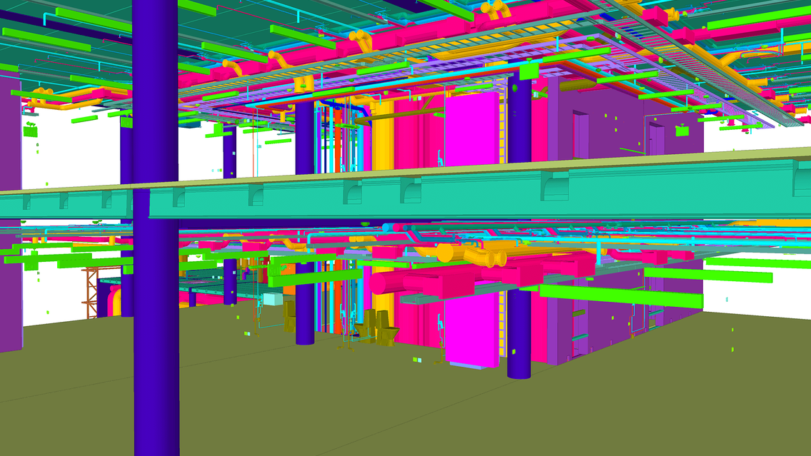
There is a huge amount of MEP technology in a modern office building, and its coordination and installation as designed would have been close to impossible without BIM. MEP installers were very happy with the quality of coordination and the constructability of design, which enabled BIM-based installation as designed. Building information models helped a great deal to communicate with clients during user meetings, for example.
The project was scheduled with Vico Schedule Planner, and a weekly 4D calendar was created based on that with Tekla Structures. This enabled accurate visual monitoring of the frame phase, and the project parties were able to quickly grasp the current situation on site. In addition, frame supplier Nordec used its own ERP extension to monitor fabrication in Tekla.
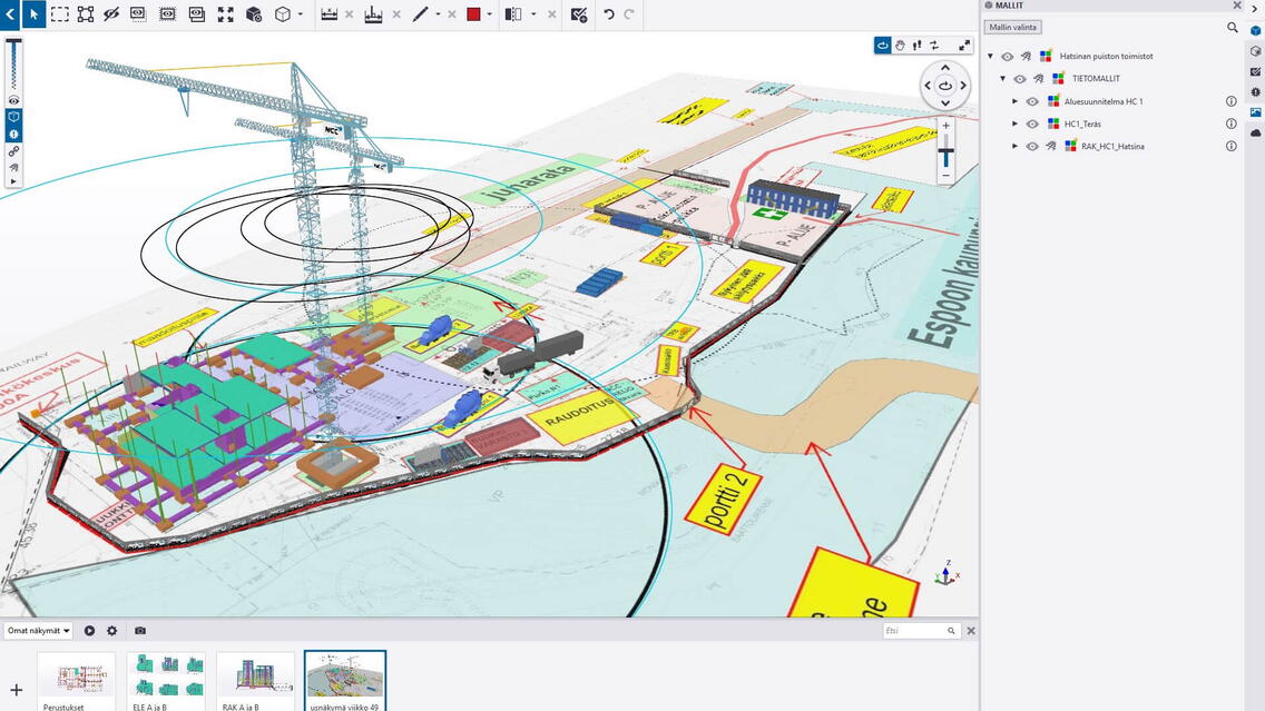
Trimble Connect’s Status Sharing tool was used to visualize not only the construction schedule but also the design status and to compare the two. In addition to visualization, model-based follow-up enabled as-built quantity surveying. Site layout was created with SketchUp, and the frame phase was matched in Trimble Connect using the Status Sharing tool, and this allowed planning the order of various work phases. Moreover, yard and earth works were coordinated with storage logistics in Trimble Connect. This was done with a photogrammetry 3D model produced from drone footage. Indoor installation order was visualized and the VAC equipment impact area mapped in colors in Trimble Connect.
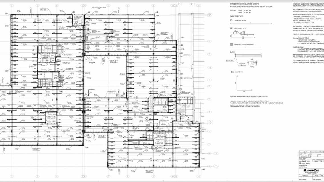
The project used IFC models from different design disciplines in construction preparation, including quantity surveying and mobile use. NCC followed up on the CIP works with Trimble Connect Status Sharing, and formwork from Tekla Warehouse were used in the structural model. Factory progress was updated via SAP ERP and entered into the model. Element progress was shown phase by phase in the model once the items were discharged from the factory system. During the project, quantities were transferred from the Tekla model to cost estimation and model information to MIS/ERP systems and fabrication planning (material optimization, delivery planning, scheduling) and shop fabrication. The construction site marked the received and installed items in the model. IFC and DWG files were received for reference from the architect, the geo, HVAC, electrical and sprinkler system designers, the steel detailer and the municipal engineer. Hole reservations were made by using specific IFC files handled in Tekla Structures Hole Reservation Manager. Steel frame supplier’s model was used as reference by structural design in IFC format. A-Insinöörit used its own custom components for precast reinforcement and accessories and structural steel connections. The structural model was submitted to the steel frame supplier in IFC format, and the precast manufacturer received initial information for the thin-shell slabs for the parking garage directly from the model by Model Sharing. The Tekla model was also used to communicate the status of precast design. In structural analysis, information was mainly transferred manually by modeling, but the parking garage frame, for example, was transferred directly from Grasshopper. The number of iteration rounds varied according to structure. Some structures were good to go, while piles and foundations, for example, needed several iteration rounds. Information was transferred from Tekla Structures to A&D and vice versa, but not for the same structures, i.e. data transfer between the software was one-way. The client received both the drawings and the building information model.
All design disciplines shared an updated IFC model of their models once a week. The architect used the models from the structural designer and other design disciplines on a day-to-day basis as the primary source when reviewing the design. PDF/DWG formats were only used for support after the BIM review. In principle, all the necessary information has been found in the building information models. The designs have been coordinated with the help of a BIM Coordinator in monthly coordination meetings, and the design disciplines have updated their models according to what has been agreed in the meetings.
Many Trimble tools were introduced to Finland in this project
It would have been difficult to accurately calculate excavation masses without drone footage and the Trimble Stratus software, and thanks to new technology, all project parties could share an up-to-date idea of the project and disputes regarding actual quantities were avoided. Trimble Stratus helped with layout design and works planning, too, when looking for an optimal location for a concrete pump truck, for example.
A first in Finland, the site got to use the Trimble XR10 with Hololens 2. For the first time, the models and designs literally opened before our eyes. The installer no longer needed to imagine the MEP or partition wall, for example, because it could be visualized exactly as designed. For example, in the mechanical room, it is now possible to confirm the space needed for the ventilation equipment or multi-layered MEP installations. With the help of Trimble XR10 virtual hard hat, the site was able to conduct tours and inspections safely considering the pandemic-related restrictions. Moreover, the XR10 enabled making notes in the model during a site tour.
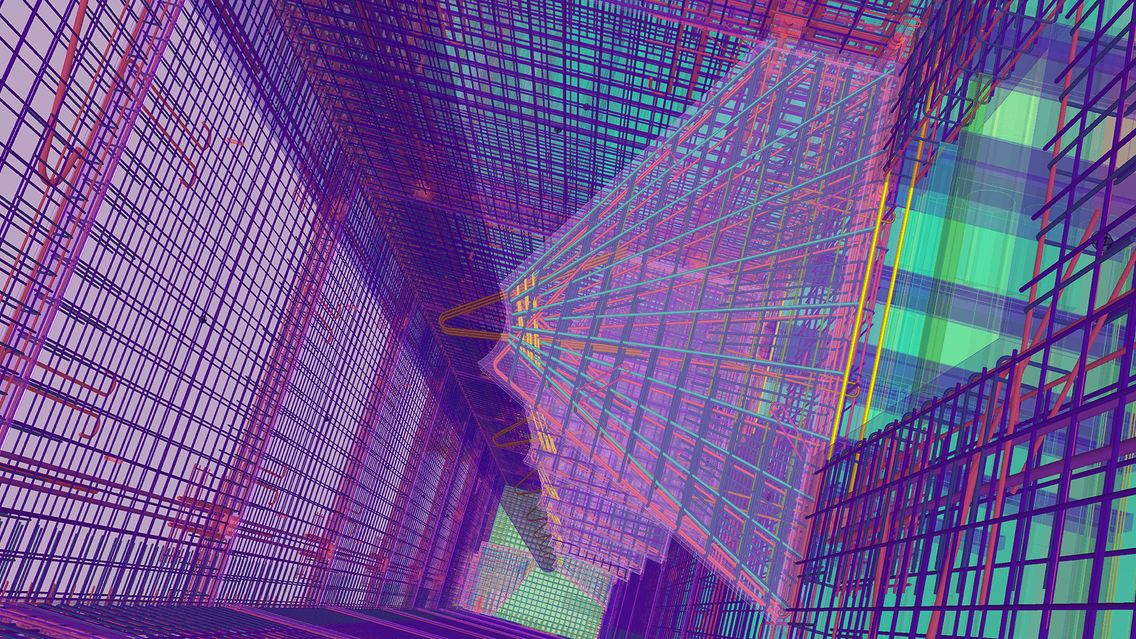
In addition, Trimble Sitevision helped with earthworks on site. The device was test-used in reinforcement inspection, too, resulting in a small rebar deviation spotted compared to the design. Trimble Business Center was found necessary to use in the device, because the software enables the transfer of all designs into the global coordinate system to view in the device. Trimble Connect mobile version was frequently used on site on a day-to-day basis. Thereby the models and designs could be pocketed anywhere at any moment.
BIM-based construction measurements and laser scanning were tested during several phases of the project. Hollow core slab level was surveyed by scanning with the SX10 robotic total station, and the point cloud was compared with the target surface in the model in Trimble Connect to survey the need for surface casting. Compliance with the tolerances of the track-side precast concrete wall was verified by laser scanning over the train track to ensure smooth installation of the final facade. Mechanical room’s ventilation pipelines were scanned using the X7, and automatic “scan-to-BIM” point cloud conversion was tested.
Trimble also brought Spot the robot dog by Boston Dynamics to visit the site, being tested by Trimble and Aalto University researchers as part of the Building2030 development program. The robot’s features and capacity were tested on the stairs, by remote control from New Zealand, and by scanning the premises with an X7 installation, for example. NCC submitted all necessary models for the research project so that point cloud and BIM utilization can be developed further.
Project parties:
Contractor: NCC Suomi Oy
Client: NCC Property Development Oy
Architectural design: Cederqvist & Jäntti Arkkitehdit Oy
Structural design: A-Insinöörit Oy
Electrical design: Optiplan Oy
Manufacturing and installation of steel structures: Nordec Oy
Steel detailing: Sweco (Nordecin tuoteosakaupassa)
HVAC design: Ramboll Finland Oy
Precast: Parma Oy
Sprinkler design: Festec Oy
