Project overview
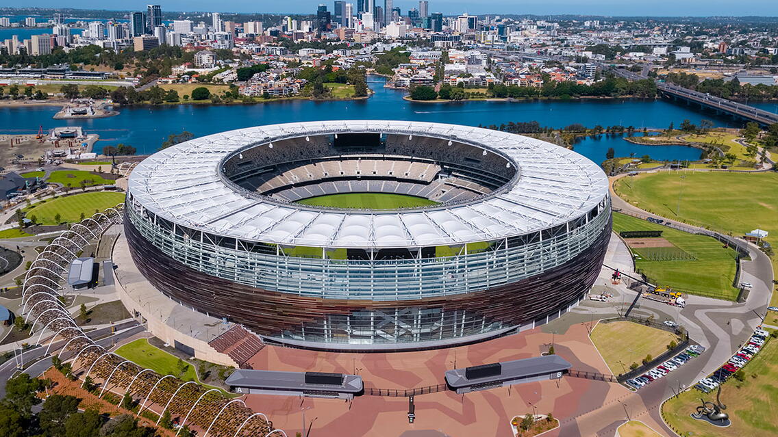
Western Australia’s highest profile and most eagerly anticipated development, Optus Stadium was opened in January 2018. It all started in 2011, with the Western Australian State Government announcing plans to build a ‘fans-first’ 60,000 seat multi-purpose stadium on the Burswood Peninsula and banks of the Swan River.
The five-story tall facility is the third largest venue in Australia and has the flexibility to host major AFL (Australian Rules Football), cricket, rugby union and league, football (soccer), athletics and entertainment events. It completes the greater Sports Park, together with the new children’s playgrounds, community spaces, plus restaurant, bar and café facilities available year-round. In delivering, the BIM enabled engineering scope of work, Arup and PDC were involved from the design through to construction completion stages, working within the Westadium Consortium led by Multiplex with architects and other consultants under the DBFM (Design Build Finance and Maintain) Project Agreement. The following BIM timeline explains the involvement phases.
BIM Enabled Engineering
Engineering a complex development, on the brownfield site with a number of project requirements and stakeholders, also included a set of additional prerequisites in developing the engineering solutions.
• The stadium structures were to be designed and built fit-for-purpose, whilst creating value added benefits to the project and client throughout the product’s lifecycle.
• The roof was to be designed for Perth’s climate conditions, easy to construct and install.
• Engineering solutions were to adhere to the architectural concept of a unique precinct, recognizable as Western Australian across Australia and worldwide.
• Stadium features to be safe, efficient and quick to erect.
• Fans interests adhered to as the highest priority.
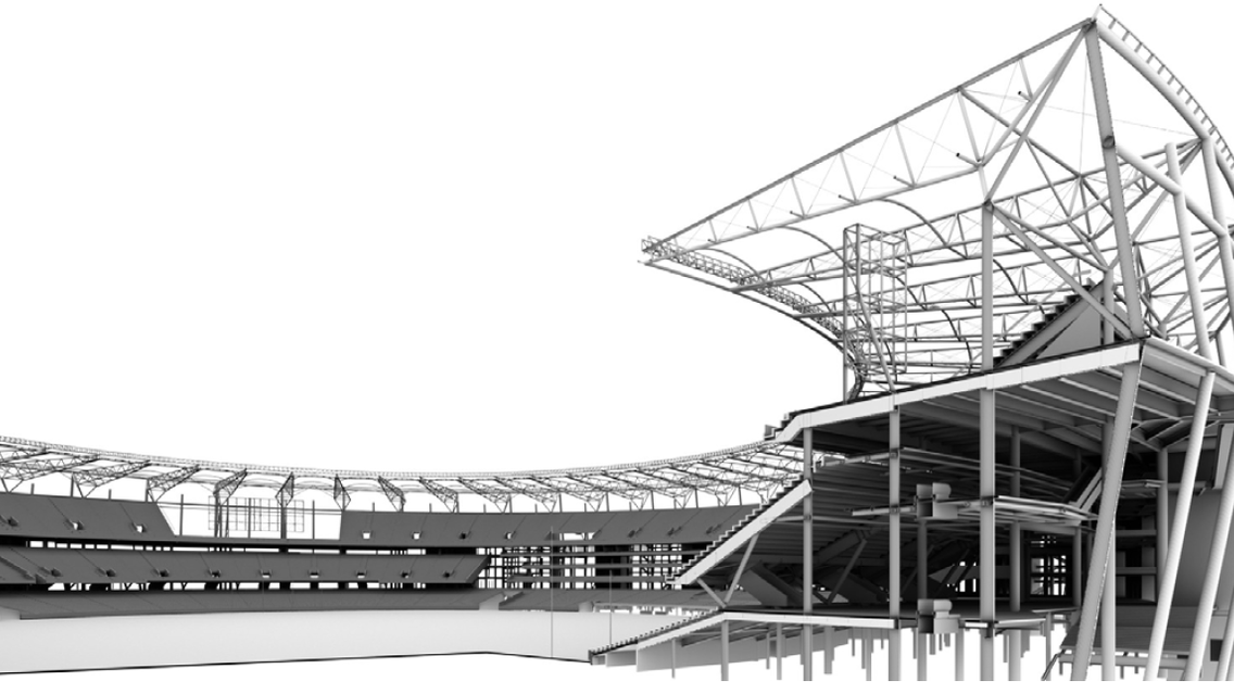
The engineering team worked with the builder in the pre-bid stage to develop the overall BIM workflow and documentation, and brought Multiplex and PDC to go further and implement the BIM strategy throughout construction and operational phases of the project. The stadium Tekla model was broken up into eight (8) quadrants including the four (4) stand quadrants of North, South, East and West and the four (4) remaining quadrants breaking up the roof structure. These quadrants enabled the design and detailing teams to improve agility while maintaining the overall schedule.
The engineering team has put in place a process that provides significant benefit from the use of the model through increased design collaboration and coordination whilst at the same time lessening the burden of the increased deliverable requirements, for example COBie. This provided the builder with a clear direction, compliance checking and assurance that the project could be delivered to meet both the aspirations of the overall client and to develop their knowledge of BIM. This association meant that architectural and structural refinements could occur in parallel without losing element-to-element connectivity or resulting in the separation of modeling parts which avoided timely rework at each design update.
As an outcome of the digital workflow, complete coordination and alignment of design between architect and engineer was maintained throughout. Through consultation with Multiplex, it was determined that for speed of construction (given the tight timeframes imposed by the client), the structure would consist of reinforced concrete lateral stability cores, with a composite steel and concrete frame. This made it possible for the steelwork to be erected quickly with the slabs poured on permanent metal deck formwork without back-propping allowing the fit-out of the structure to quickly follow.
The bowl structure of the stadium was designed using precast prestressed concrete plates, which made it possible for more than 3,250 elements to be constructed and stored off-site for “just in time” delivery. The bowl geometry was rationalized to limit the number of changes in plate rise whilst maintaining spectator sight-lines, and plates were designed to maximize use from a limited number of molds, resulting in a highly efficient and economical solution.
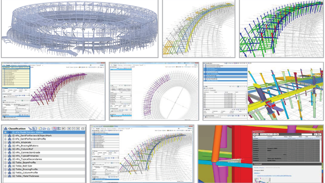
Arup went on to develop the Solibri shop model validation process with Multiplex and their sub-contractors to streamline the review process for structural steelwork and saving on average 50 percent of checking and rework engineering design time. All of the produced steel design work was detailed within the integrated team to streamline communication between designers and Tekla model approvers. The team worked closely with all involved to develop a workflow, by breaking up the structural engineering deliverables into discrete packages, based on the floor level and quadrant, and the steelwork Tekla models were reviewed in 3D. Comments and amendments from all were then returned to the steel fabricator using Navisworks to provide clear and concise comments to be incorporated by the steel shop detailer. The BIM modelling was highly regarded by the State Project Team: “The time spent on developing the virtual stadium, enabled resolution of coordination between all sub-consultants and sub-contractors in the construction phase.”
Tekla for the Optus Stadium
Implementing the model validation due to the vast amount of information from various consultants and sub-contractors was pivotal in a successful delivery of the Optus Stadium development. Deploying the Tekla and other model validation tools such as Solibri was for the following reasons:
Validation of the Stadium Model The ability to check that the models were built correctly and as per the comprehensive BIM standard, in line with the EIR’s from the client.
Weekly Progress Clash Checks The ability to monitor clashes and understanding if the latest developments were part of the design or implementation process. The application and approach enabled the client to preview and be involved in the engineering process.
Model Sharing Tekla Ver21 Cloud-based model sharing allowing the ability to tap into global resources improving on schedule and costs by allowing multiple offices to work simultaneously
Model Compare and Collaboration Tekla modeling enabled all design consultants on the project to understand changes within the models in a timely manner and flag any questions and concerns. The stadium experience and the manner in which we deployed the tool and then disseminated the capability within the teams defines our efficiency that is easily transferable to other developments regardless of the size.
Tekla BIMsight Tekla BIMsight was used as the coordination tool to capture engineering comments and link it into the Tekla model.
We deployed Solibri to regularly monitor weekly changes in other consultants’ model as a powerful co-ordination tool in a fast-track project in which models are constantly under development. In addition, the design Project Managers tracked the progress of deliverables and modified invoicing related to new changes. In the implementation and fabrication stage, the shop detailers were able to import the IFC model and arrange painting elements according to the model classifications and schedules. The available information included: quantities (length, volume), profiles, date, stage of construction, grade, revision status, and review status. The example of produced models passed on to the steel detailers for fabrication are showing the same information, resulting in a more efficient workflow that saved time and removed the need for re-modelling.
QA Process and Model Audit in conjunction with Tekla Organizer, Beam Extruder and Import Attributes, we utilized in-house tools to check and update member sizes and embedded attributes such as part mark, shear studs from Excel into the model. In addition, this process checks the entire model for new elements added, amended and deleted parts. A report is then created, values applied into the model and sent through to the steel detailer. The following shows the process of updating the data in Tekla from schedules, and checking discrepancies between the Tekla and Engineering data. Once those are resolved the updated attributes of amended elements are generated.
Five Most Interesting Facts
• A ‘fans first’ focus in developing the concept design and applying innovative technologies.
• Designed for an initial capacity of 60,000, the stadium is safeguarded for the potential future addition of 10,000 seats.
• The total of 50,000m3 of concrete and 15,500 tons of structural steel were used to construct the multi-purpose five-tier stadium.
• A bronze façade is made of anodized aluminum to reflect Western Australian unique geology, interweaving it with 15,000 LED lights that can reflect team colors and sync to music.
• The stadium development project was completed three weeks ahead of the schedule.
About the companies
Arup were engaged to provide an additional scope to help formulate the project’s BIM strategy as part of the bid response. The basis of the service was to provide an overall BIM strategy that would allow Multiplex to benefit through the implementation of BIM on the project. Due to the State’s Project Team, high aspiration of LOD 500 which was one of the first in Australia, Arup went on to develop a streamlined delivery workflow for Analysis to Design to Database to Model to Drawings, and required documentation.
The PDC Group was engaged in the implementation phase for two critical aspects of the project. The BIM Management for Multiplex on the Stadium, including training and knowledge transfer to their project team, and 3D modelling and steel detailing in close collaboration with the engineering, architectural and fabrication teams for the +15,000 tons of steel supply.


