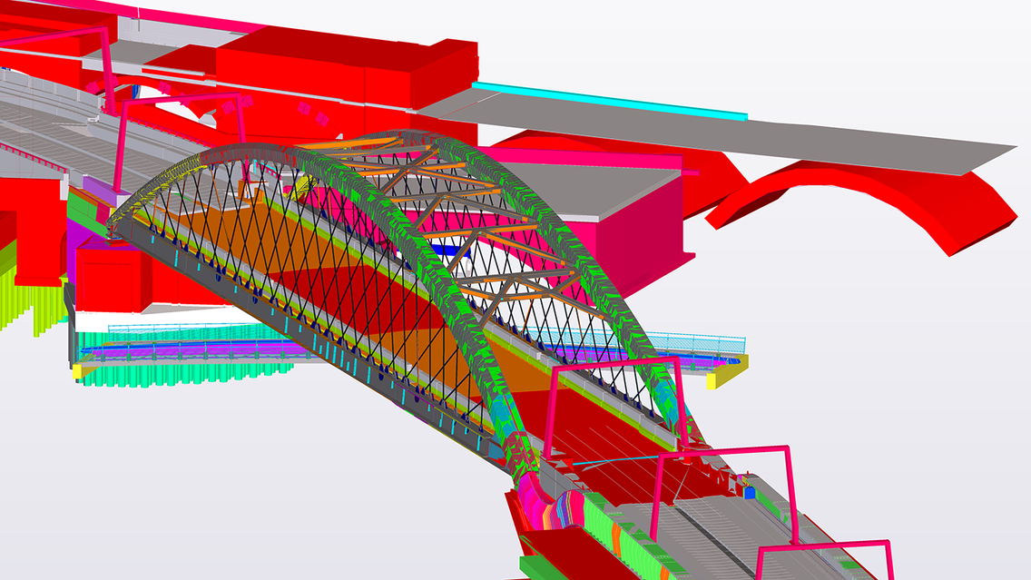
Network Rail’s multi-billion pound North of England Program (incorporating various projects including the Northern Hub, North West Electrification and Trans-Pennine Route Upgrade programs) is an ambitious attempt to transform rail connectivity in the north of England, delivering hundreds more trains to run each day and providing space for millions more passengers a year. The Ordsall Chord project is a key part of the program.
The Orsdall Chord will for the first time directly link all five of Manchester’s city-center railway stations: Piccadilly, Oxford Road, Deansgate, Salford Central and Victoria. Due to open at the end of 2017, it creates improved north-south rail connectivity, removes conflicting operational moves to the south of Piccadilly Station, and allows a number of new rail services to be introduced.
To achieve this, a short length of the Chord will be supported on a new viaduct, and the existing Victorian brick arch railway viaducts that it connects will be extensively altered over a large part of their length. In total, 3.2km of existing railway track, almost entirely supported on viaduct, is to be altered. New structures will be built to accommodate 350m of new track, and a further 345m of existing viaduct will be widened.
BIM Modelling Process
1. SURVEY DATA
Using topographical and point cloud data, the base model of the existing infrastructure was developed (using Bentley AECOsim as the primary modelling tool).
2. ARCHITECTURAL INTENT
The architectural intent was provided as part of the planning submission for the TWAO. This was principally in the form of 2D planning drawings and pdf design guides. The data was produced in coordination with the design and construction teams to ensure efficient, buildable details while staying true to the architectural vision.
3. DESIGN INTENT
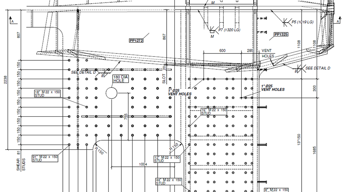
The design intent (or outline design) model was produced in Bentley AECOsim using a combination of the survey data (to produce the model of the existing infrastructure), the documentation that communicated the architectural intent and the engineering input required to refine the geometry of the structures. 2D outputs (in the form of drawings) were then produced using ‘cuts’ from the 3D models and annotated using Bentley Microstation.
4. INTERDISCIPLINARY DESIGN REVIEW
As this is a large scale multi-disciplinary infrastructure project, it was paramount to ensure that all of the various disciplines were coordinated. While each team had access to work-in-progress information from the other disciplines, the IDC review process allowed all of the design leads to come together and review the various areas together. A federated BIM model was used to facilitate these meetings, with issues and outcomes recorded on an IDC certificate.
5. DETAILED DESIGN (STEELWORK)
The early appointment of the steelwork fabricator (Severfield UK) and the collaborative behaviors that were adopted by the Northern Hub Alliance allowed the design team unprecedented access to information at a very early stage in the design that wouldn’t normally be available until towards the end of the design phase. It was recognized by the project team that the core technology platform adopted did not lend itself to the level of detail typically required by the fabricator and others in the civil engineering supply chain. Due to the detail required for the design of the steel structures, the project adopted Trimble Tekla Structures as the modelling and detailing platform. It was quickly recognized that as Tekla Structures was the software used by the fabricator, they would be able to offer assistance in the development of the design models. In turn the fabricator’s detailers would be able to absorb important information about the design and the way the design had developed ahead of needing to construct a fabrication model/details. To this end, detailers from the fabrication team were embedded into the design teams and authored the design models (with the designer retaining the ownership of the model).
6. DETAILED DESIGN (CONCRETE)
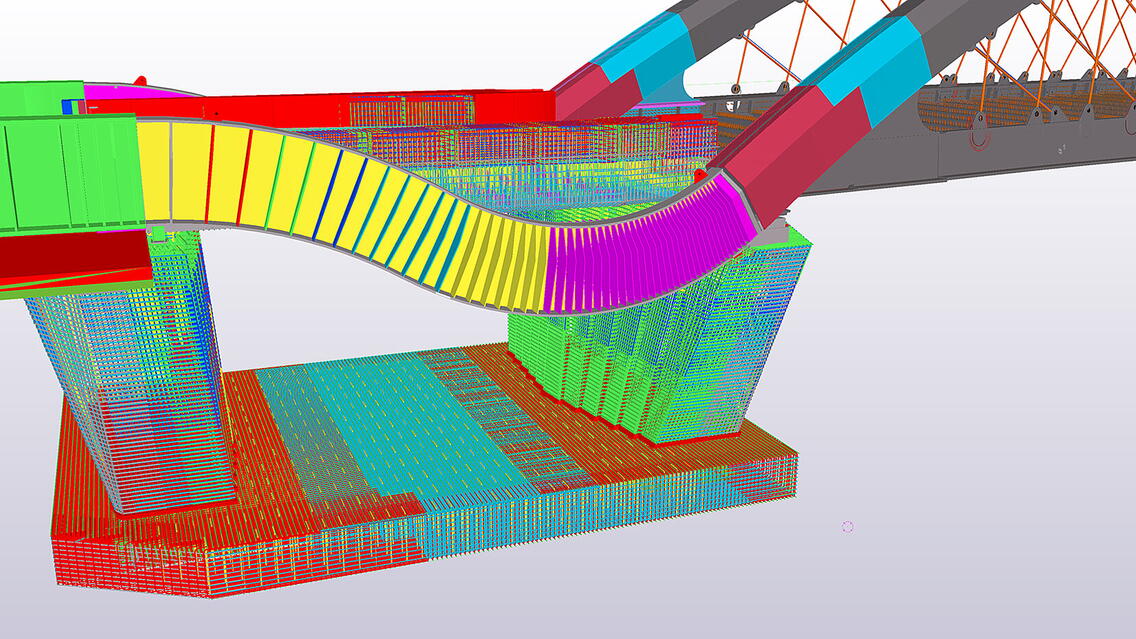
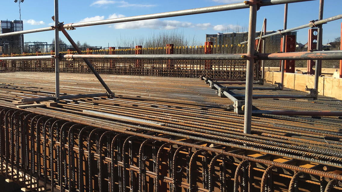
The Ordsall Chord structures have a number of interested and geometrically complex details that were created as part of the architectural design for the scheme. The majority of these details formed part of the reinforced concrete structures (either in precast or in-situ concrete). This complex level of detail required a platform of detailing reinforcement to such a level that the design team could visualize every bar. While considering various options, the design team decided to adopt Tekla Structures for the concrete detailing as well as steel detailing. This had the added benefit of being able to interface directly with the steelwork models (authored in the same software) where structures have combined steel and concrete elements. The concrete detailing work was undertaken by the AMMJV design team.
7. SUBMISSION FOR CONSTRUCTION
The “approved for construction” packages of information for each of the structures on the scheme consisted of pdf and native microstation versions of the drawing package, the BIM model(s) used in the coordination and copies of the Tekla Structures models (steel and concrete versions). A conscious decision was made to issue the models as part of the construction information due to the complexity of some of the geometry. This allows the construction team access to as much information as possible in order to build the works.


