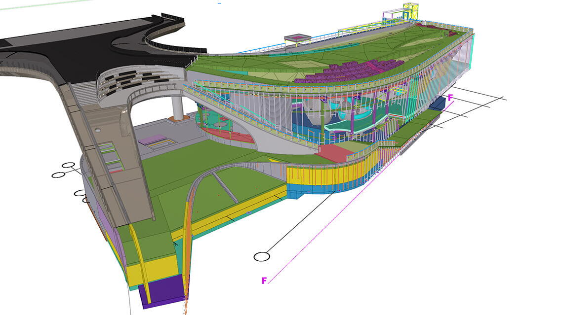
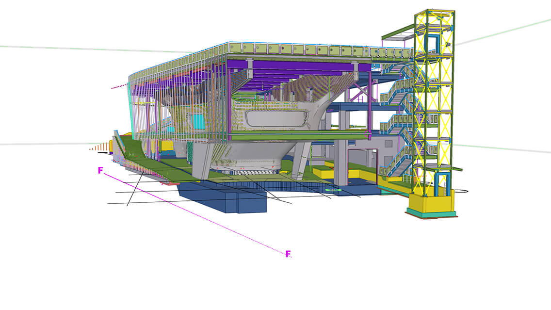
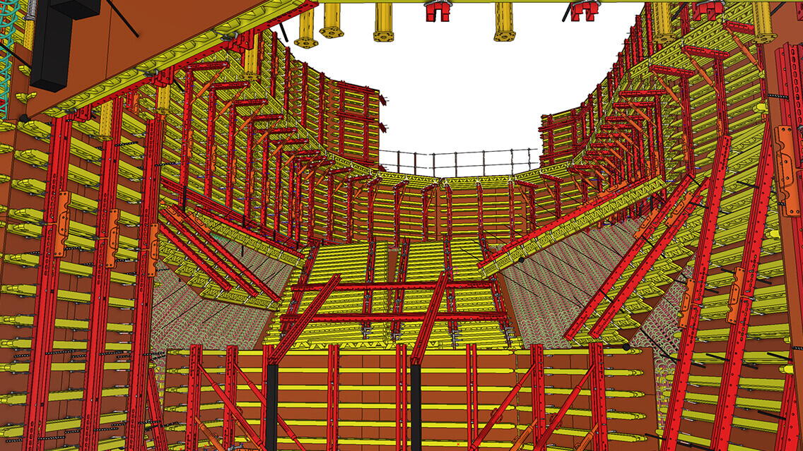
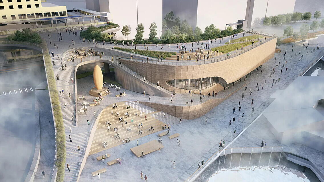
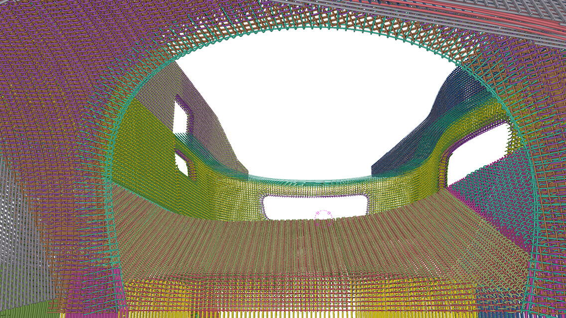
A 50,000-square-foot exhibit space featuring sharks, rays, and other animals and ecosystems from the tropical Pacific. Integrated city's elevated walkway, the structure's roof will be a public plaza with unimpeded views of the sunset and Mount Rainier. At ground level, a circular port called an oculus will allow passersby to peer into a 325,000-gallon coral canyon teeming with thousands of fish and invertebrates. The habitat's (tank) structure included a 2-foot-thick curved concrete wall and was built with 355 tons of rebar and 680 cubic yards of concrete, or four times the amount used on a typical core. Since the shell-like tank shape forms essentially had no straight edges, Turner and its project partners created 229 panels shaped by a CNC router and foam-glued to Peri Group backing, then sprayed with truck bed liner material to create a uniform surface. Turner leveraged Tekla, Rhino, and Grasshopper 3D software to create the double-curvature concrete geometry for the 362,000-gallon habitat (tank).
Challenges and achievements
- Challenge and Success Part 1 (Technical) - Given the project's unusual shape (nonlinear / non-orthogonal), the digital tool was essential for building and vetting everything through the model. All aspects had to be figured out digitally, and the pieces had to be 100% fabricated to be built on-site. However, there weren't enough precedents to guide us, so we iterated and conducted experiments to ensure perfection. Our team began by understanding the capabilities and stability of the different software applications at our disposal. Each software may excel in specific areas such as modeling, analysis, or detailing. It ensured that our chosen software was compatible and could exchange data seamlessly. Tekla Live Link enabled us to link the different software tools together effectively. We have developed a straightforward workflow that outlines how data will be transferred and synchronized between the software applications. The process involved transferring files, using live links, or utilizing interoperability features.
- Challenge and Success Part 2 (Collaboration) - The most challenging aspects our VDC team encountered was gaining the field team's trust and confidence in the digital model and actively collaborating with them to adapt to the new process. Establishing protocols and methods to regularly review and validate the model as a team was significant in ensuring that it accurately reflected the construction documents and facilitated efficient coordination. Consequently, the project was successful due to the camaraderie we've built across the team working on it. Everyone left their egos at the door and sincerely helped and listened to everyone's expertise in overcoming the daily challenges faced. Instead of pointing fingers, the team embraced a collective "we" mentality. We took mistakes as lessons to improve upon and quickly turned things around. Everyone was in this together.
Using Tekla software
Tekla Structures was an optimal solution due to its great interoperability with various software applications (Tekla Live Link) and model-sharing platforms (Trimble Connect). A more efficient and streamlined design-build situation was achieved by leveraging the strengths of other software modeling capabilities and utilizing Tekla Structures' detailing tools through Tekla Live Link. This empowered us to explore complex geometries, perform accurate analysis, and prepare models for fabrication with enhanced precision and efficiency.
- Bidirectional Data Exchange: TheTekla-Rhino-Grasshopper workflow allows for bidirectional data exchange between the software tools; any modifications made in Rhino and Grasshopper can be synchronized back to Tekla Structures, ensuring that the geometry remains consistent through the design-build process. This interoperability facilitates an iterative design-build approach (between the designer and GC). It supports efficient problem-solving design and fabrication iteration and optimization. It allowed the reduction of wordy RFI explanations and miscommunication. Due to complex geometry, this bidirectional data usage was necessary because our contractual document was provided as a 3d model in Rhino from LMN (architect).
- Linking Rhino (and Sketchup) Geometry to Tekla Structures: Vetted geometry created in Rhino (and Sketchup) was exported to Tekla Structures for further detailing and fabrication preparation. Rhino geometry can be easily transferred to Tekla Structures using Tekla Live Link (Tekla-Rhino-Grasshopper), a direct integration plug-in.
- Detailing and Constructability Analysis in Tekla Structures: Within Tekla Structures, the linked geometry from Rhino (and Sketchup) was the foundation for subsequent detailing and constructability analysis. Tekla Structures provides a comprehensive suite of analysis tools for creating accurate concrete elements, formworks, steel embeds, rebars, and more. These tools enabled the creation of detailed installation sequence drawings specifically developed for the tank's formwork and concrete lift drawings. Moreover, the information derived from these drawings was also leveraged to feed the fabrication process of complex formwork through CNC technology.
- 3D model for Model-Based Layout: The vetted model was then delivered to surveyors to generate points using Trimble Field Link to be linked to Robotic Total Station for layout purposes.
- Cohesive Model Sharing Platform using Trimble Connect: Tekla's built-in function to share models through Trimble Connect was instrumental in enabling the project team to access the latest version of the 3D model for viewing and analysis. The workflow was especially crucial as the project relied entirely on a model-based layout. Equipped with tablets, the field team could utilize the model on-site at any time, providing them with a clear understanding of the scope of work that would have been challenging to ascertain in 2D. The Trimble Connect functionality allowed the team to measure, identify spot elevations, and calculate concrete volumes at their fingertips, eliminating the need and time for constant communication with the office.

