All design disciplines accurately modeled
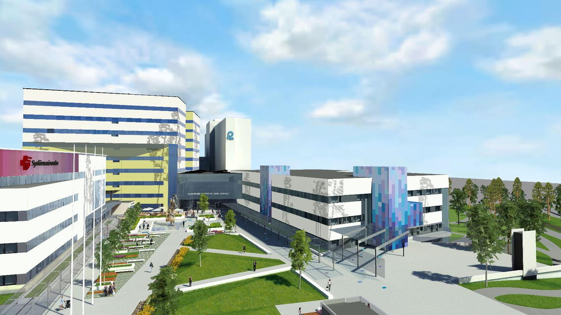
The large front yard project for the Tampere University Hospital (Tays) includes both new construction and renovations. The area will have three completely new hospital buildings, so called D, N and L wings, as well as a new underground parking facility. Two old hospital buildings and the yard’s underground section has been demolished. All this is being designed and built in the middle of a busy hospital environment that must remain functional throughout the project.
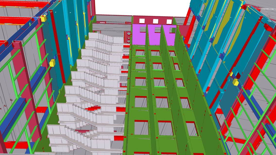
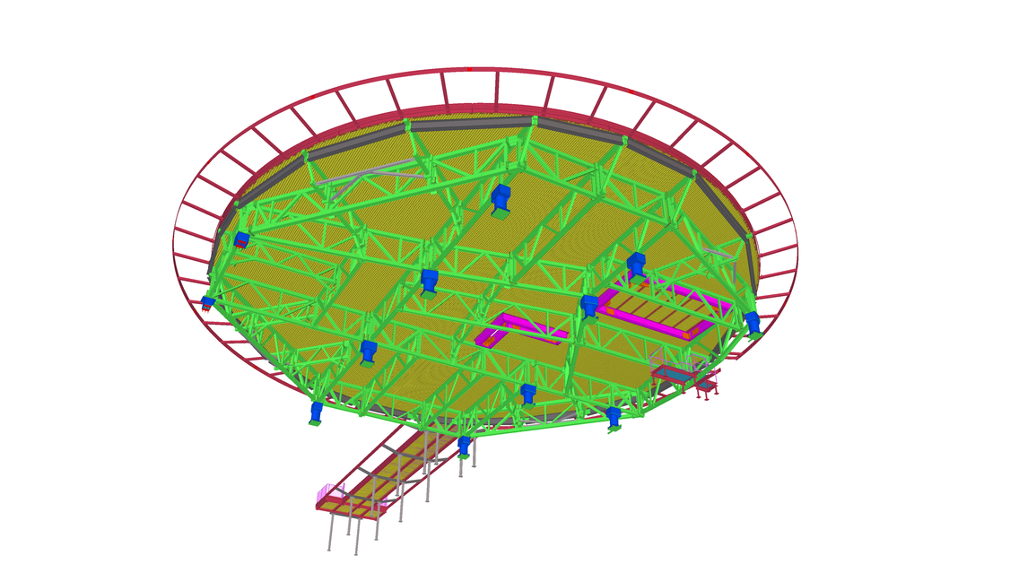
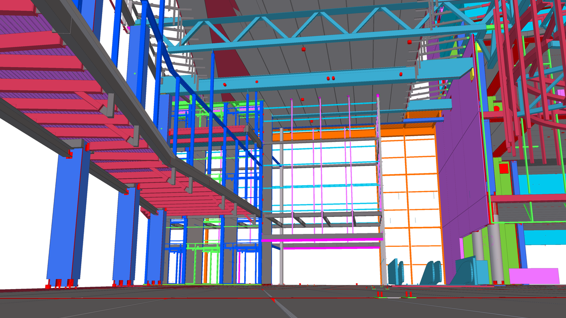
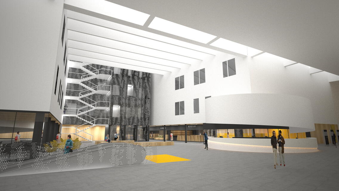
The biggest new building, D wing, is architectonically diverse, leading to challenging structural solutions. The frame consists of a column and beam frame, stiffening lift shafts (one of which is steel framed), hollow-core slab flooring, steel-concrete composite structures, steel trusses, and facade panels made of concrete. The most challenging structures include large glass roof and curtain walls, complex diagonal shapes and cantilevered structures in the main facade, tall pressure walls, complex ground-base slabs, and multi-floor gateways to the other hospital buildings. One of the specialties is a round 33-meter diameter helipad. Additionally, the huge amount of hospital and HVAC equipment has played an important role in the project, affecting the structures and their positions.
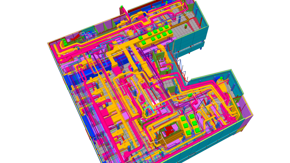
All design disciplines are accurately modeled in this project. Even hospital technology, and flying sectors for helicopters (as space reservations). Every two weeks, the BIM coordinator creates a combined model of all the design disciplines, making sure that the designs fit together. Combined models have played a significant role in design coordination, and the same combined model is used on-site. End users have been engaged in the design process by entering the space through a virtual cave at the architects’ offices.
Construction started in August 2015 with large rock excavations. The project will be completed phase by phase during 2017–2019. Hospital building D that will house deliveries and newborn care is expected to open at the beginning of 2020 and the parking facility in two stages in 2018 and 2019.
Construction amongst hospital operations
The design and construction of the D wing is influenced by the fact that the new building is connected to a fully functional hospital, and the First Aid operating 24 hours a day. The safety areas needed for e.g. precast unit installations, had to be taken into account, and as a result the building had to be moved 8 meters from its original planned location. Interfaces of the various new and old buildings has been very challenging due to varying elevations, and the fact that e.g. the D wing interlaces with the parking facility. The design of the neighboring building structures, which are designed by another team, have to be taken into consideration all the time. This has been managed with the help of combined structural models, meaning that the IFC files of the L and N wings as well as the parking facility are being used as reference models in the D wing Tekla model. Additionally, cloud point models of the old facades have been used to manage locations of the new
structures in relation to the old ones, and the necessary old structures have been modelled. The structural design manager uses the same Tekla multiuser model as the designers to monitor the projects. In addition to various kind of IFC models, the Tekla models have been used to produce a large number of drawings.
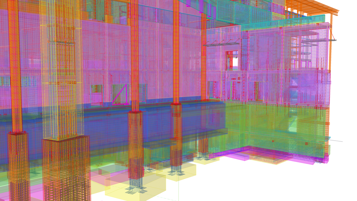
Structural modeling has been stretched to the level of construction accuracy, and all building materials have been modelled using Tekla. The models have been delivered to be utilized further by the main contractor, the CIP contractor, and precast and steel suppliers as well as for use in external design projects such as design of the infrastructure and a new tram route outside the parking facility. The subcontractor modeled all the CIP reinforcements using the structural designer's IFC model as a reference, to get the precise rebar schedules for the procurement directly from the model. Cast-unit specific reinforcement models are viewed on iPad using Tekla Field3D on the site. Smaller sectional models are easier to operate on mobile devices than large ones. The contractor also produces reinforcement drawings from their model for their own use.
Instead of traditional hollow core slab drawings, the structural designer sent a native Tekla model to the precast supplier to be used as input data in detailed design. The slab’s main geometry is taken directly from the model. The structural model has also served the needs of the main contractor. For example, the steel assemblies are checked in a Tekla BIMsight model delivered by the structural designer.
Design status is monitored on-site using a model that includes project status visualization. The structural designer produces IFC models with color-coded unit statuses. The IFC format of the structural model has also been used on-site to view crane capacity. Building information models have also been very useful for project collaboration in technical design meetings held on-site every two weeks. Outside the site hut, the master builder carries an iPad to view the Tekla Field3D model and the mechanical equipment technicians use the models on their mobile devices to check the piping routes.
Without BIM, management of demanding geometries, combining four buildings on various levels and coordinating the various design areas would not have been possible. In addition to the challenging structures, the D wing alone encompasses thousands of channels for the building systems. Managing the locations and levels of these channels would have been impossible in 2D. At least the main contractor, the CIP contractor, and precast and steel suppliers have been able to utilize the structural models. Not only in the “traditional” way by obtaining quantities for procurement and transferring geometry data to slab design and CNC, but also widely on-site on computers as well as on mobile devices to visualize the project.
Avoiding material waste was one of the big benefits of modeling the CIP reinforcements. The rebars in the model could be listed accurately and delivered ready-bent on site.
Project parties:
Owner: Pirkanmaan sairaanhoitopiirin kuntayhtymä
Structural design and detailing: A-Insinöörit Suunnittelu Oy
Repair design: A-Insinöörit Suunnittelu Oy
Geotechnical design: A-Insinöörit Suunnittelu Oy
General contractor: SRV Rakennus Oy
Architect: Alliance of Arkkitehtitoimisto Tähti-Set Oy
MEP design: Alliance of Granlund Oy & AX-Suunnittelu
Design of hospital mechanical systems: Saircon Oy
Cast-in-place contractor: Betonirakenne Oinas Oy
