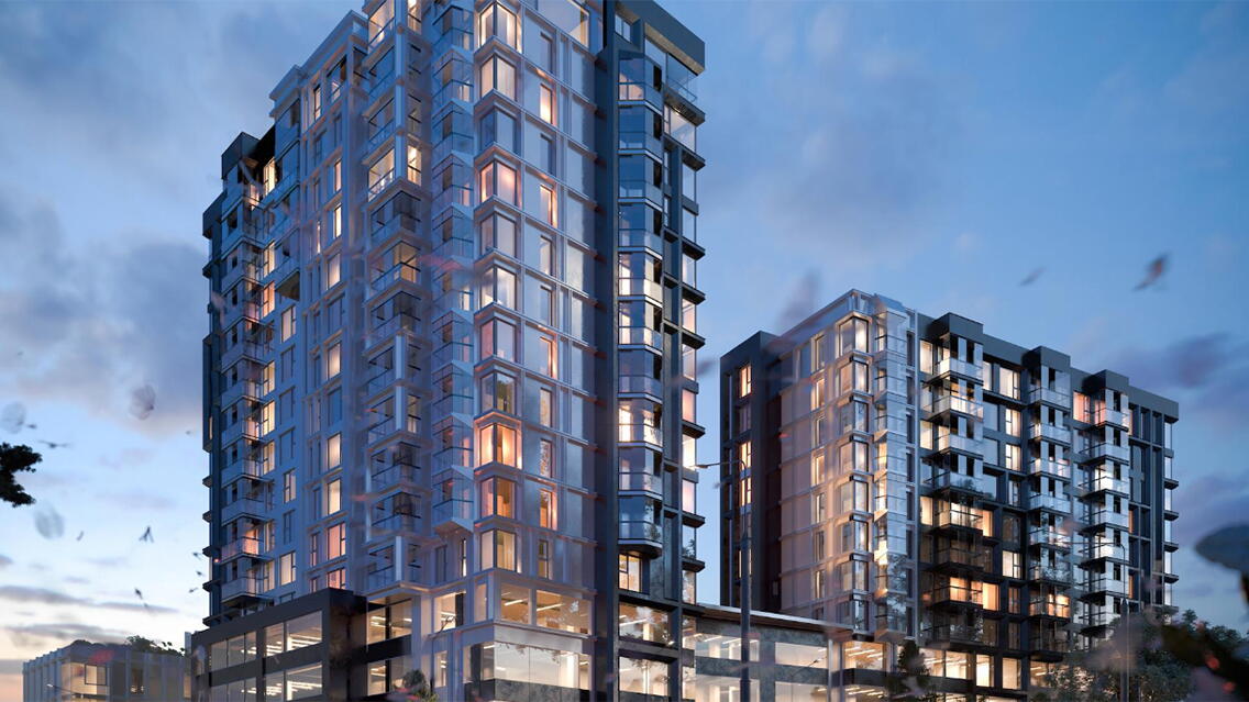
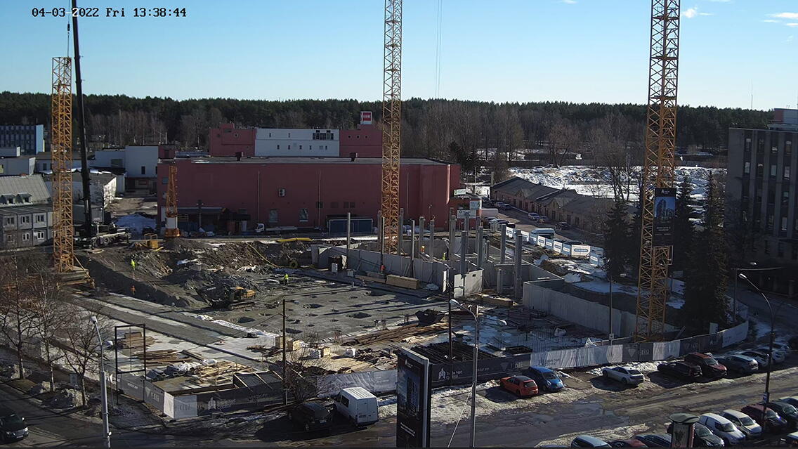
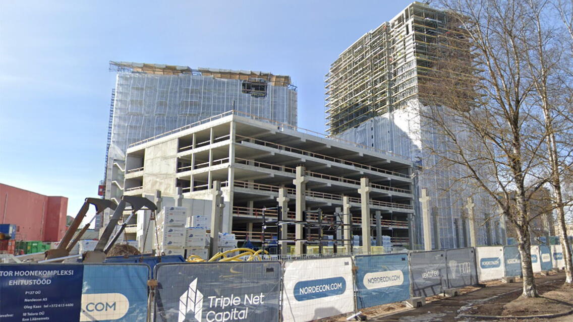
This project involves a multifunctional building complex interconnected by an underground parking level. Sweco Projekt AS's role in the project was to design the entire load-bearing structure (except for producing product drawings). In addition, Sweco Projekt AS also designed the heating, ventilation, and cooling, as well as the water and sewerage systems.
The above-ground portion of the construction consists of four parts (volumes):
1. A 16-story high-rise with office and commercial spaces on the 1st to 4th floors, and apartments on the floors above.
2. A 12-story lower-rise with office and commercial spaces from the 1st to 4th floors and apartments on the floors above.
3. A parking garage with an intensive green roof.
4. Saku 2 office building.
Like various other high-rise buildings recently constructed here, our building has a significantly more complex shape. Its fractured façade required an irregular arrangement of load-bearing elements (columns) to be compatible with the ground-floor parking spaces.
It was also an ambitious goal to make most of the project prefabricated (except for the parking garage). Moreover, the project used a variety of structural solutions – post-tensioned cast-in-place concrete (for the parking garage), pre-stressed solid slabs for thermal break details at balconies, and steel balconies protruding from the building's façade.
Use of BIM in design
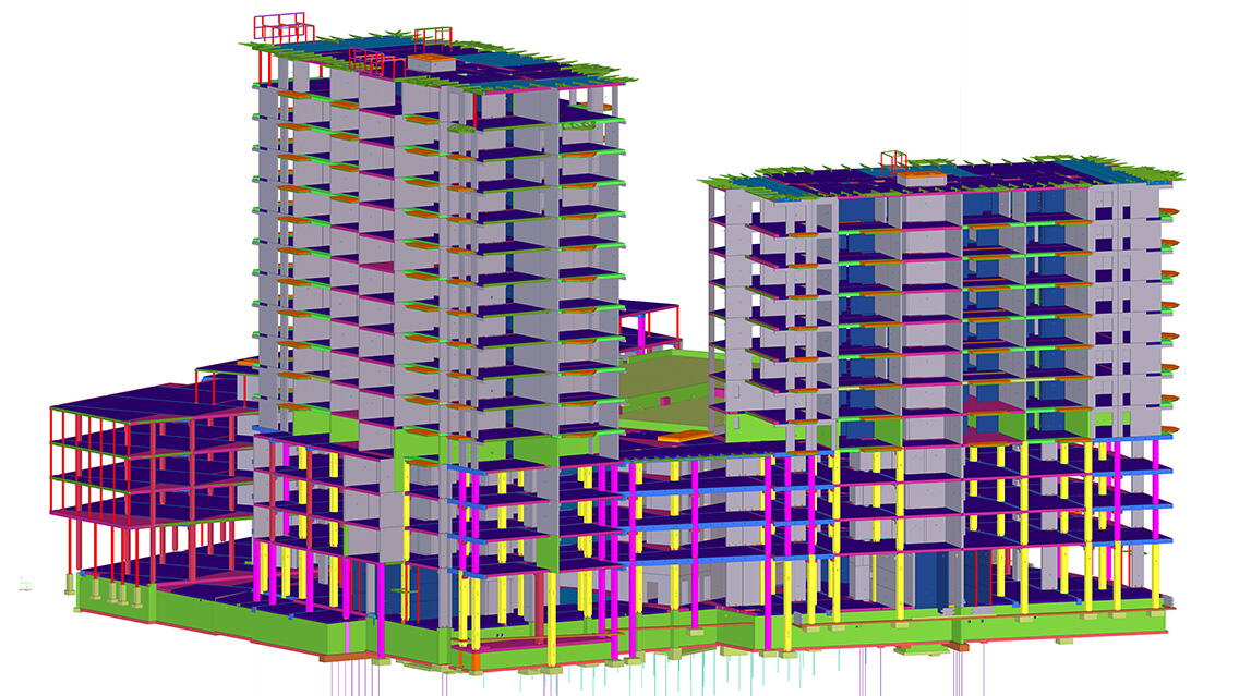
The geometric design of the building structures was established using an architectural sub-model as the foundational reference. Sub-models encompassing architecture, structures, HVAC, and plumbing systems were utilized to perform clash detection, ensure accurate integration of piping within shafts and concealed spaces above suspended ceilings, and facilitate the creation of required openings throughout the structural framework.
The geometry of the tower cranes was incorporated into the model, and a separate IFC was created for each. This enabled builders to visually identify which elements required installation after dismantling the cranes and plan accordingly.
Our model accounted for the tower cranes' radii and load limits, which was crucial in designing the geometry of the prefabricated elements. Representation filters were employed to verify that the designed elements did not exceed the cranes' load capacities.
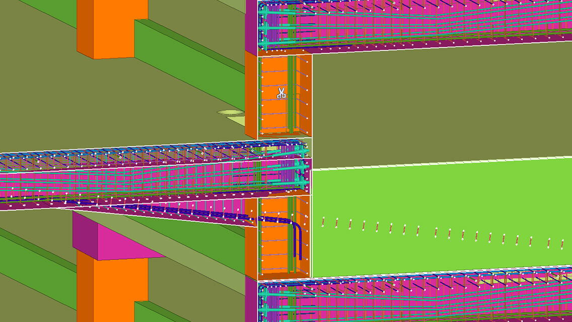
Arro & Agasild Inseneribüroo OÜ created product drawings for the reinforced concrete elements using the model sharing function within our model. Our team was responsible for defining and modeling the geometry and connections of the elements while they provided detailed designs, added lifting lugs, and produced the final product drawings. To prevent conflicts, elements that were not yet modeled were initially locked. Once modeling was completed, these elements were also locked. A User-Defined Attribute (UDA) was added to concrete columns for the type of reinforcement to be implemented to aid the product draftsmen in accurately modeling the reinforcement.
The project was segmented into four phases, each representing a distinct part of the complex, with an additional breakdown into floors in the Tekla Organizer tool. These categorizations served as filters during the modeling and drawing stages and were instrumental in generating comprehensive lists for the main contractor.
Collaboration based on the BIM model
No specific data content requirements were set for the project, but in collaboration with the main contractor, the necessary data content was added to the structural model. This data was used for model analysis, construction work planning, and volume calculations. Trimble Connect was used to analyze the models, which were accessible to all project participants (architecture, structures, etc.).The main contractor also used the ToDo function to address issues that arose during the model checks.
Because the creation of product drawings and the construction coincided, the precast reinforced concrete element manufacturers were provided with lists of necessary products exported from the model. This method enabled them to pre-order the products before the product drawings for the precast concrete elements were issued.
Using different solutions on the construction site
Per the builder's request, an information field was added to the precast reinforced concrete elements to indicate the completion of the product drawings. This assisted in ordering elements and organizing assembly work. The structural model was updated every Friday, providing the main contractor with a progress update every Monday morning.
QR codes were assigned to the elements to be assembled and then affixed to the completed elements. Scanning the QR code allowed easy identification of the element in the model.
Innovation and novelty
This project required seamless collaboration and coordination. An unconventional and new aspect was the engagement of a company, selected by the main contractor, to produce product drawings from our model while we continued designing the rest of the building.
Sustainability
The project will ensure LEED Gold compliance.
Project partners:
Engineering office: Sweco Projekt AS (load-bearing structures without product drawings) Other project parties:
Client - Mithandrir Invest OÜ
Main Contractor - Nordecon AS
Architecture - Kadarik Tüür Arhitektid OÜ
Product Drawings - Arro & Agasild Inseneribüroo OÜ

