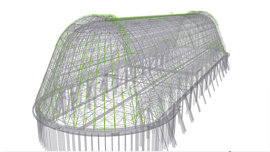
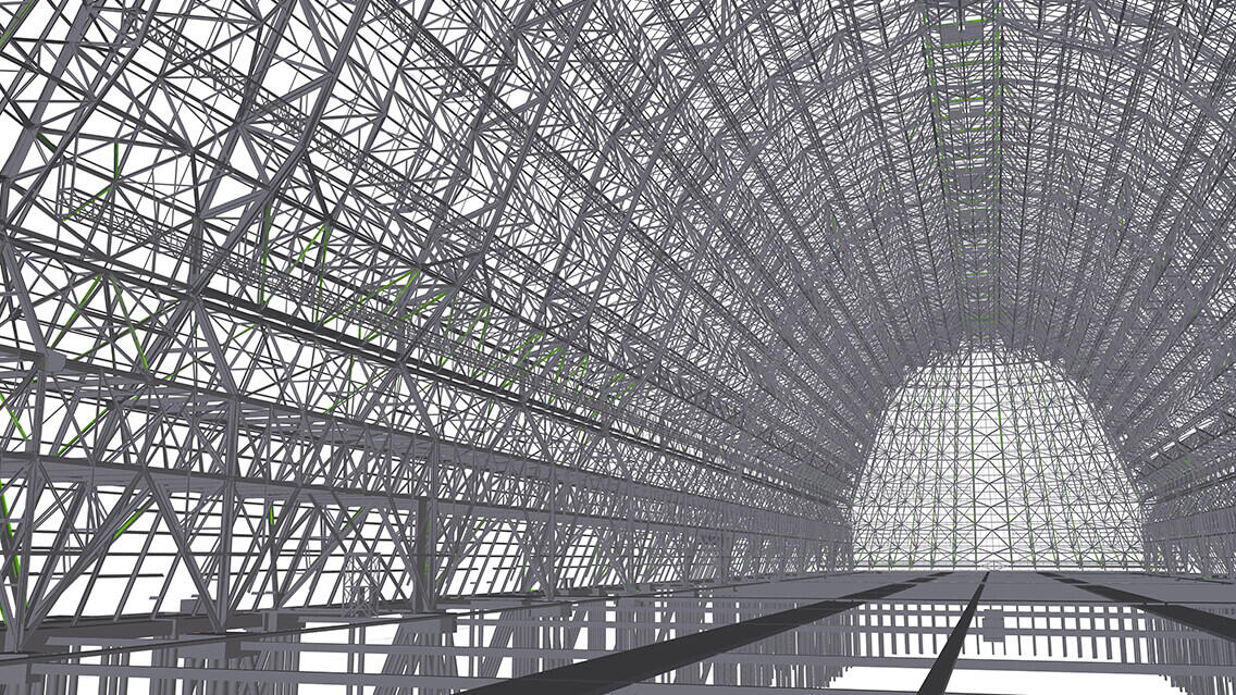
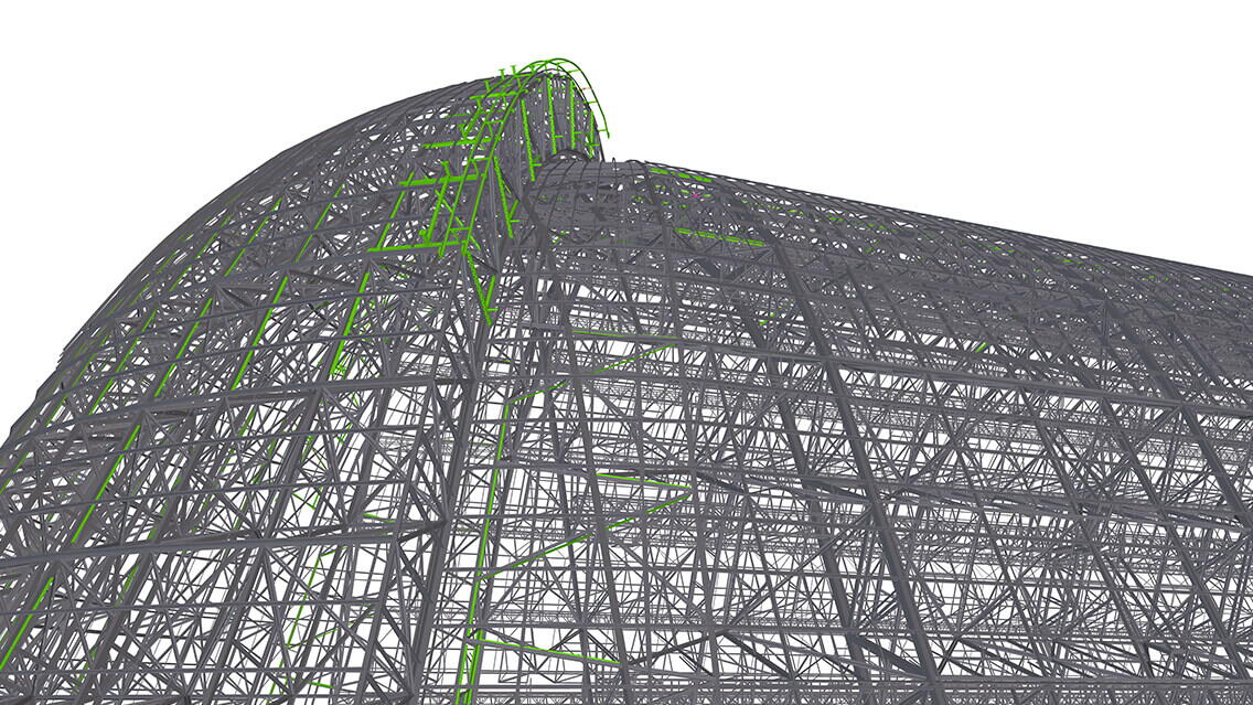
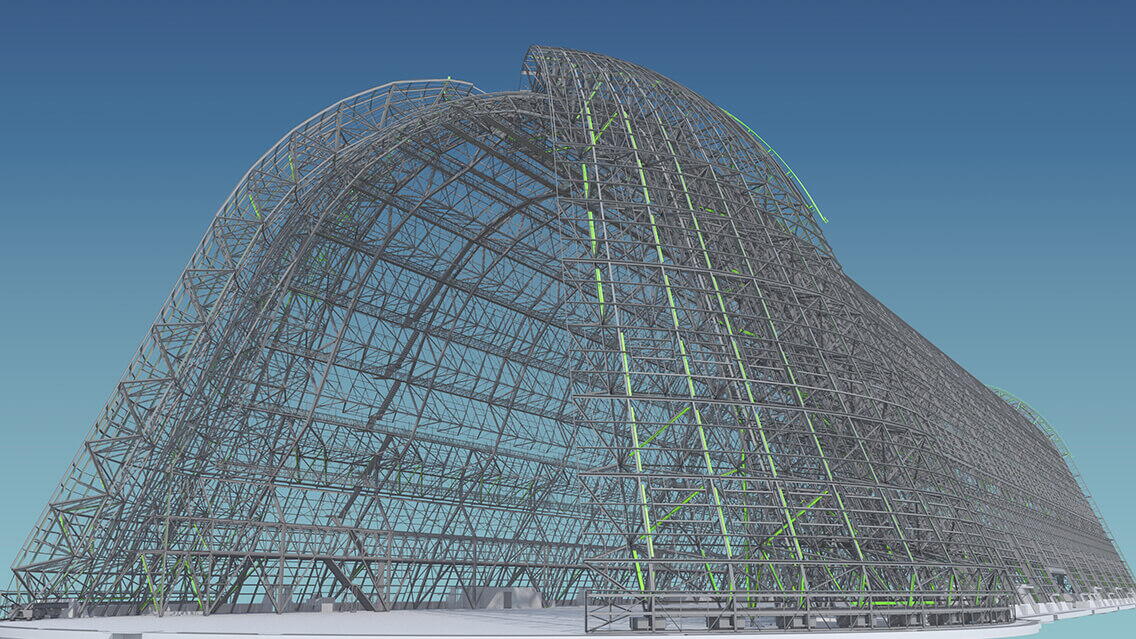
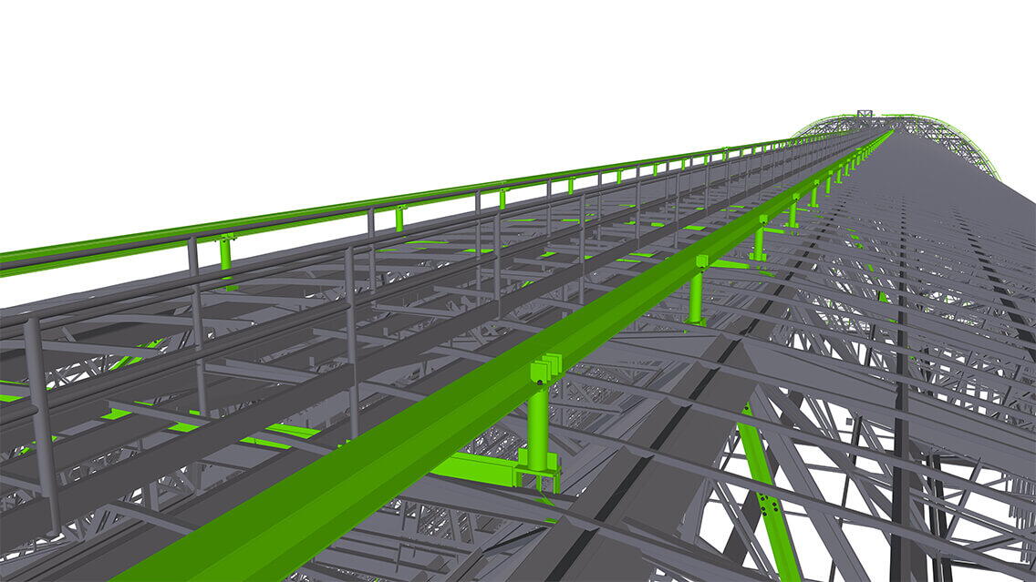
It has become an iconic symbol of California's Silicon Valley and is recognized as one of the world's largest buildings. Built-in the 1930s as a naval airship hangar for the USS Macon, Hangar One now resides within the NASA Ames Research Center. Featuring steel girders covered with galvanized steel, the hangar is an engineering marvel. Its massive size and distinctive design have made it a prominent landmark in the region, visible from miles away. It served as a storage facility until its decommissioning in 1994 due to the discovery of harmful PCBs (Polychlorinated biphenyls), leading to the removal of its roof to address the contamination issue.
In 2012, local authorities explored the possibility of demolishing Hangar One entirely and reconstructing it to its original design. However, after careful evaluation, the decision was made to retain the hangar and remove the asbestos shading that had been added as protection against PCB (Polychlorinated biphenyls) contamination.
Hangar One stands as a testament to NASA, Google, and local authorities' collaboration in preserving a historic landmark. The ongoing restoration aims to maintain its historical significance while creating a functional space for scientific research, technological innovation, and education at the NASA Ames Research Center.
Challenges and achievements
- One of the primary challenges faced was the limited level of detail provided by the original hand-drawn structural drawings from 1931. To address this issue, the Engineer of Record utilized these drawings to create a theoretical Structural stick model in Revit. This model served as a baseline for setting out the existing structure interface and determining the required structural reinforcing within the Tekla model.
- Another significant challenge was to interpret design drawings and address design discrepancies. With a gap between the 1930s drawings and the as-built structure, the lack of documented RFIs or as-built changes posed uncertainties and changes that occurred during the existing construction. Through meticulous investigation, advanced technologies like Point Cloud scanning and Revit model exports used within the Tekla model environment, and close collaboration among stakeholders, the project team successfully navigated these challenges.
- DBM Vircon’s most significant challenge involved ensuring the correct size of steel reinforcing before submitting drawings for approval. This was important because the site team would be required to physically move the steel to the designated location. Because of the limitations on member length and overall weight, which required manual transportation of the steelwork, the DBM Vircon team collaborated with Schuff Steel to physically carry the steel.
- DBM Vircon initially evaluated the feasibility of transporting the material through the scaffolding with two individuals carrying a weight of sixty kilos (140 lbs). The task was physically demanding, considering the length of the members, which were required to be no longer than ten feet or 3 meters. To meet the design as well as the logistical limitations, CJP splices were required to be implemented that exceeded the length/weight criteria - however the review of the location and quantity of splices was pertinent in ensuring the implementation of splices, as the process of CJP (complete joint penetration) welding is both time-consuming and costly.
Using Tekla software
By utilizing Tekla, the construction costs and time will be significantly reduced. By leveraging Tekla's capabilities, such as site measuring and decision-making independence, the reliance on external resources and associated energy consumption is minimized and reuse of material was maximized. Consequently, the project duration is significantly reduced, resulting in substantial power savings. The detailing and modeling of project, which could have potentially lasted three years, was shortened by approximately two-thirds.

