Complex geometry at Birmingham New Street station
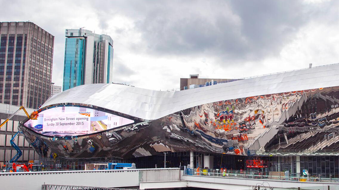
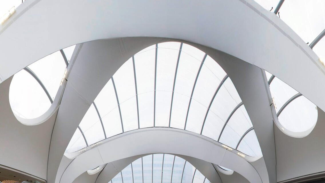
The South Entrance structure forms one phase of the five-year Birmingham New Street station refurbishment project. As the busiest station in the UK outside of London, the original station was dark, unwelcoming and overcrowded with poor access for passengers. The new station is bigger, brighter and lighter, providing passengers with a fantastic first impression of the city.
The site for this phase of the construction project was extremely challenging in its own right, with all sides being locked tight up against other live elements.
Complete collaboration and virtual build saves time and cost
With such a complex structure, in terms of both geometry and logistics, the only way to complete the project successfully, safely, on time and within budget, was to ensure all parties could work closely and collaborate with shared information. This meant that SK Detailing Services and NewSteel Solutions had to inter-operate with Network Rail, Simco (Main Contractor), WSP (Project Architect), AKT (Project Engineers) and all other Second-Tier contractors to ensure that the project was fully designed and detailed "virtually" off-site, and all interfaces between trades had been considered and resolved prior to any materials arriving on-site. The time and cost saving benefits of this "virtual build" were huge in ensuring that the interfaces and scheduling of all trades ran exactly as planned and without delays.
Building the structure from reference models only, not drawings. No 2D drawings were used to set-out any of the structural elements. Instead, only reference models were used and shared by all parties, to ensure that there could be no mis-interpretation of data, or incorrect input.
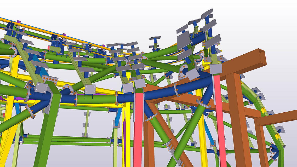
Firstly the existing structure was surveyed in 3D and imported into Tekla to create the baseline, ensuring the new structure would interface perfectly with it. Then WSP and AKT produced reference models, providing firstly a 3D representation of the curved cladding "skin" which set the structural steelwork positions, in order to follow these three dimensional curves. Secondly, the 3D design analysis reference model was imported, with the forces applied for the steelwork section sizes and with the connection forces to be designed to. Using this approach, within Tekla we could then design and position the structure perfectly to suit these parameter models.
BIM co-ordination in connection design
Due to the complex geometric nodes, BIM model sharing had to be used to provide Abacus Design, the connection designers, with the setting out geometry to design the individual connections. And as the roof and wall shape varies through the entire structure, no two nodes are the same, meaning the BIM models were invaluable in the connection development. The designers’ ability to interrogate the BIM model, to check geometry, allowed the design engineers to visualise and design the connection in true three dimensions, and ensure all elements of any nodes were accounted for.
BIM co-ordination during fabrication process
BIM model sharing was also used at fabrication, planning and installation stages. Due to the complex geometry it ensured that the NewSteel Solutions’ production manager had up-to- date BIM models of all assemblies to give an instant visualisation of the pieces being fabricated, which gave the fabrication shop the ability to determine before even starting work on a piece, what it should look like, and where areas of difficult fabrication or limited access would be. This meant they could pre-fabricate small sub-assemblies first and, that any parts with difficult weld access were pre-welded, totally removing weld access problems from the start.
Obviously all workshop information was still issued in the traditional fashion, with Tekla producing all the necessary assembly drawings, part and shaft drawings, templates and reports required. But above this Tekla provided NC data for all parts to be laser cut, ensuring the best possible fit for the likes of the scalloped and profiled tube members.
The BIM model also proved invaluable by giving instant access to three dimensional check dimensions, rather than huge quantities of drawings with only 2-dimensional views. This gave the workshop access to any dimension, at any time, without being restrained by only the views and dimensions provided by the fabrication details.
BIM co-ordination during phasing and installation process
These same abilities were also afforded to the installation teams, who initially drew heavily upon the BIM model to determine the installation sequence and phasing. BIM models were used not only to determine the "buildable sequence" but also to determine the crane and steelwork unloading positions, due to site logistics being so constrained. The NewSteel Solutions site teams worked closely with SKDS to phase the entire structure, and ensure that there was sufficient working area and optimised crane position at each and every erection stage. These construction stage, planning models were then used to formulate the exact installation order for every single piece, and determine the requirements for the temporary support structure needed to ensure everything was erected safely.
The temporary support structure model was also exported from Tekla, and shared with the on-site survey team, who using total stations, ensured that the temporary structure was built in exactly the correct position, to exact co-ordinates, so that when the permanent structure was positioned on top, it was in exactly the right position also, reducing the need to try and forcefully align and level the structure afterwards, which would have proved difficult on a structure with predominantly face-to- face solid connections with tight build tolerances.
Collaboration success
Without the use of Tekla, reference models, and BIM integration, a structure of such complexity simply could not have been realised in such a short time frame. Tekla gave us the ability to link easily and seamlessly with other organisations and software, such as on-site 3D surveys, CNC manufacture processes, and 3D visualisation software.
Using the internal multi-user functions of Tekla to speed up internal processes, and embracing the collaborative and co-ordination benefits of reference and BIM model sharing, all parties involved in the project have performed their respective tasks extremely efficiently and successfully, and deliver a truly iconic structure on time and budget.


