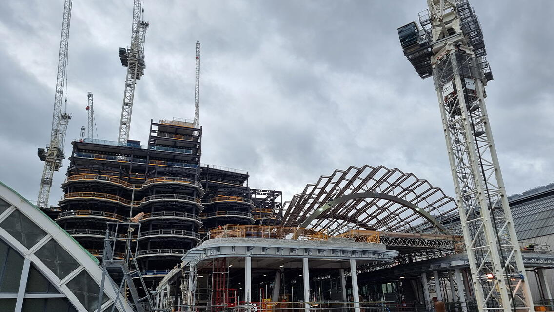
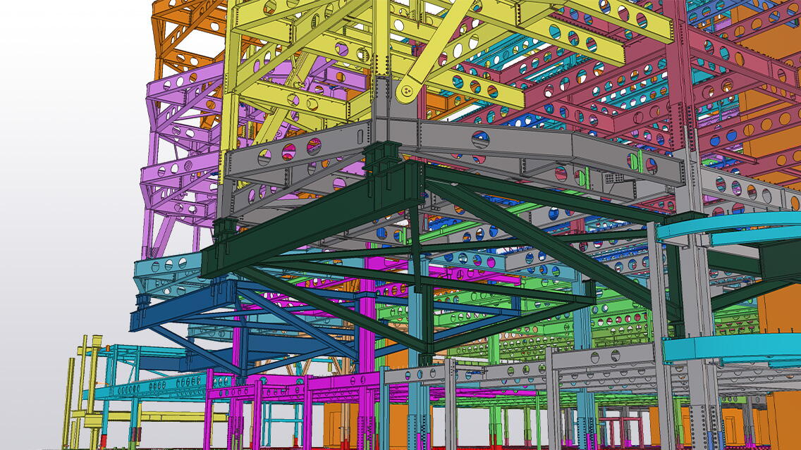
The Olympia redevelopment will see one of London’s oldest exhibition venues become home to a new cultural district, creating a hub for the arts, music and entertainment. The works, which have taken place around and above Olympia’s three main exhibition halls - which have remained open throughout - are developing performing arts spaces, affordable workspace, hotel, jazz club, independent restaurants, and shops.
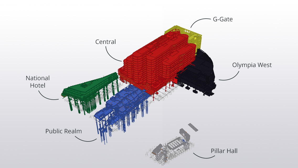
Olympia West
The roof of West Hall was removed and replaced with a new second floor with its third-floor mezzanine, creating a 4000-capacity music venue. This building was entered into the Tekla awards last year and won its category. It has been included for reference.
G-Gate
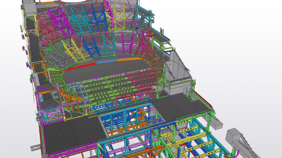
Adjacent to West Hall is the G-Gate Building. This part of the Olympia site was previously used as a car park but will now accommodate events space from ground to the underside of level 2, one of the largest new theatres to be built in London since the 1970’s from level 02 to the underside of level 08, and three levels of office space above. Aside from the complexities of creating a huge column free auditorium, complete with balconies, a major challenge has been the acoustic isolation of the theatre. Acoustic bearings have been required at levels 02 and 08, to isolate the theatre from the exhibition space below and the offices above, but it has also needed to be isolated from the music venue immediately next door.
Public Realm roof garden terrace
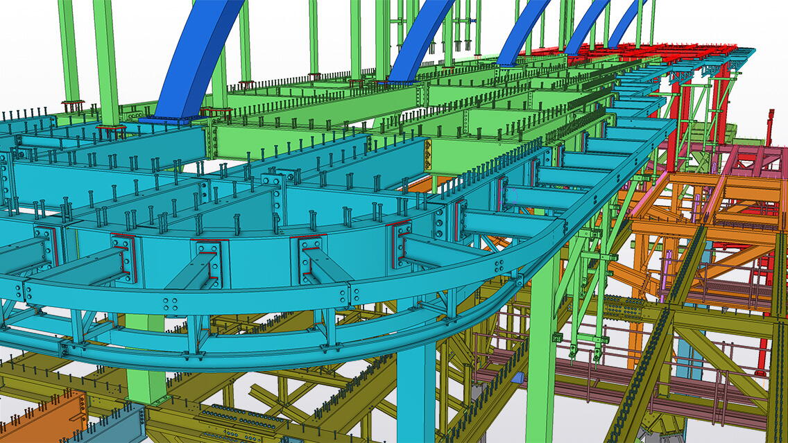
The theatre and music venue are both located at second floor level and are to be accessed from a new Public Realm roof garden terrace, which has been formed between the roof of National Hall and Grand Hall. Plunge columns were installed down through the existing structure below, and these support a series of 30m long trusses. These trusses were to be installed between and around the existing rooftop plant and air handling units, which had to remain in place and functioning, to service the exhibition halls below. These trusses allow the roof terrace to float above the existing roofs, and accommodate food and drink outlets, restaurants, and shops over two levels. The Public Realm space at level 02 is accessed by two huge steel framed staircases and escalators.
National Hotel
On the opposite side of the National Hall roof sits the National Hall Annex, where 30-No. plunge columns were installed down through the Grade 2 listed building, to support a grillage of transfer beams, that allows a three-storey hotel to float above and be independent from the listed buildings below.
Central
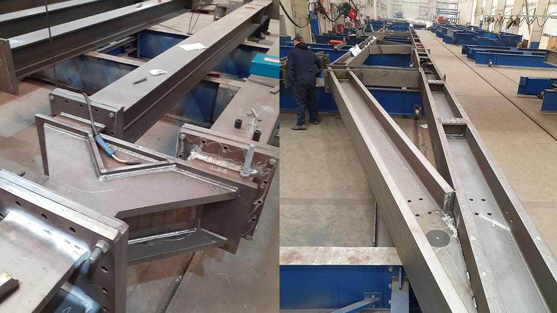
The largest part of the entire development is Central, and it sits behind the retained Grade 2 listed façade, along Hammersmith Road, on the site formerly occupied by the Empire Hall. This area links all of the other blocks together, and also provides the access route to the new underground car park, whilst incorporating exhibition / conference space at levels 01 & 02, plant at level 03 and ten levels of office accommodation above. The structure up to level 03 was extremely challenging with numerous trusses spanning up to 28m long being required, which along with five columns, that had to be installed through the glass roof of the Grade 2 listed Grand Hall, allowed the office floor plates to extend and cantilever out over the roof of the Grand Hall below. The trusses weighed up to 60T each and were delivered in halves, each being fully welded at the factory, and assembled using bolted splice connections on site.
The office levels above were divided into five lozenge shaped fingers, and were stepped in height, where two have 12 floors, two have 13 floors and the central finger has 14 floors. At the ends of each of the fingers, at level 03 the floor cantilevers out over the structure below, with the northern finger cantilever starting at level 05, when it was above roof level of West Hall and Grand Hall.
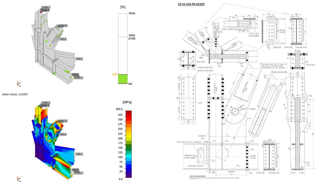
These finger cantilevers were supported on diagonal braces tying the cantilevers back into the main structure at levels 07 & 11. The finger brace connections were pinned and required huge gusset and fork plates at each level, as the solid precast floor planks had to be threaded over each connection before the next floor level could be constructed. A complex temporary support structure had to be devised, to suit the bottom-up construction sequence, with jacks to facilitate the load transfer from the temporary support to the permanent top-down support being provided by the finger braces. An extremely challenging and satisfying project to have been involved with.
Challenges and achievements
Tekla and BIM were fundamental in the delivery of the Olympia project, and can be categorised as follows:
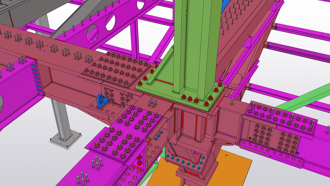
Tekla’s ability to handle complex geometry: Often when this occurred the steel involved was incredibly heavy, meaning that any errors or difficulties in processing would have been catastrophic. There were also particular cases such as the ‘finger braces’, which used pinned elliptical connections. These connections were huge but needed to be smooth. By being able to export clean cuts, this dramatically cut down the work required by the fabricators. In addition, due to the complex nature of many of the heavy assemblies, the effectiveness of Tekla to accurately find the centre of gravity can not be stressed enough. Organising transport and lifting of these assemblies without this function would have been impossible.
Tekla’s User Defined Attribute (UDA) functionality: The ability to customise the UDAs allowed Tekla to be used for much more than 3D modelling. It became a tool for communicating data, such as confirming fire protection levels throughout the building or giving a quick visual of what was already ordered. It also meant that BHC Limited’s Tekla users were able to tap into a lot of data in the model context very quickly, for example communicating new variations in the model.
Drawing flexibility and automation: The flexibility of Tekla in conjunction with the ability to set up standard settings made it easy to communicate through drawings. With such a complex structure, it became highly important that BHC Limited were able to use the drawing tools to convey information clearly and effectively.
Interoperability: For BHC’s structural engineers, Tekla’s interoperability with both Trimble and third-party products allowed them to take a complex structure and fully understand the context within their preferred engineering software. In general: Tekla Tedds was used for wind loads, Tekla Structural Designer for element design, and IDEA StatiCa for connection design. This was critical for working with other departments such as site engineering and surveys, as well as other design partners within the project. This was critical especially at node points where several members converged.
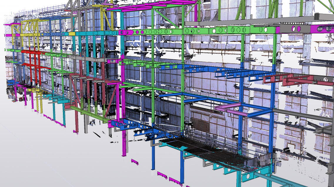
Point cloud data: The Olympia project had the specific challenge of being erected incredibly close to, and at some points through, an existing historically significant building as well as connecting to several existing structures. Point clouds were used in order to visualise data of existing structures in relation to the model, and were also used to highlight areas of concern and any clashes.
Curves: Creating complex curves on profiles was a necessity for the Olympia project, particularly as these curved members were extremely heavy and had very strict tolerances.
Multi-discipline and multi-material: The variety of products used included precast, decking, cold rolled, thermal breaks, dampening pads, couplers, lifting brackets, tools, etc. BHC both imported components from the Tekla Warehouse and created custom components.
API: There were many Tekla users involved in the Olympia project, both within the BHC headquarters and all over the world. Tekla’s API sped up repetitive tasks but also validated exports and allowed the BHC team to work accurately and efficiently, no matter the size and location of the team. Tekla’s API was essential in keeping time and costs down.
Using Tekla software
- BHC's internally developed software called TNT.
- NC files, BSWX, and DWG files were exported from the model.
- Having the ability to automatically update Trimble Connect with every write out allowed BHC Limited’s workforce and management teams the ability to view and communicate with a live model, in context with reference models from others working on the project.
- Received IFCs from Revit, from the design team.
- Custom components were created for lifting holes, drain holes, service holes, cast in plates, edge protection, and more.
- UDAs were used for: fire paint information, execution class, VO data, on hold data, previous profile data, date of profile change tracking, BHC internal coding (track and trace, environmental, etc), preliminary material order data, decking information, member utilisation.
What does BHC Limited say about the project?
“This project had so many challenges, so many areas that the individuals and BHC as a whole are very proud of. To put it simply, this project would not have been a success without Tekla. Speaking to colleagues that worked on this project through various roles, from estimators to detailers and structural engineers, from fabricators to painters, from erectors to site engineers, everyone was proud to work on it, each having their own aspect that stood out to them. Exchanging data with Tekla Structural Designer, Tekla Tedds and Trimble Business Centre under the Trimble umbrella, having a software that allows us to effectively interact with other software is invaluable.”
- Aaron Courtney, BIM coordinator at BHC Limited
