Comprised of more than 1.5 million sq ft of commercial, retail, leisure and residential, the masterplan for the Wellington Place development is set to enhance urban life in Leeds city centre.
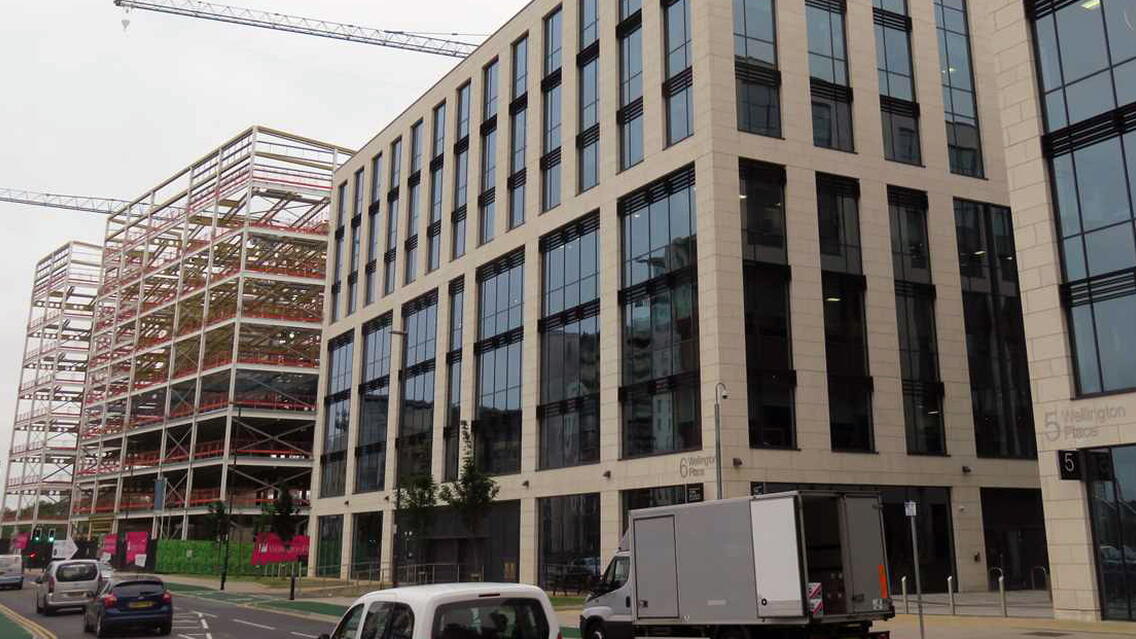
Due for completion in 2020, Wellington Place will be one of the biggest and most prestigious new city centre business quarters in Europe. The buildings are characterised with unique architecture and are specially designed to help the flow of daylight into the public realm that surrounds each unit. The exterior has wide, interconnecting, and formulated landscaping with scenic routes that incorporates the Tower Square – the development’s centrepiece.
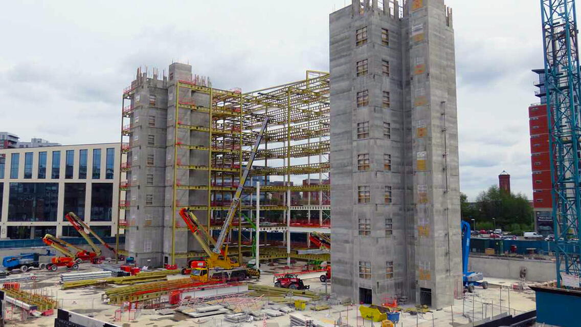
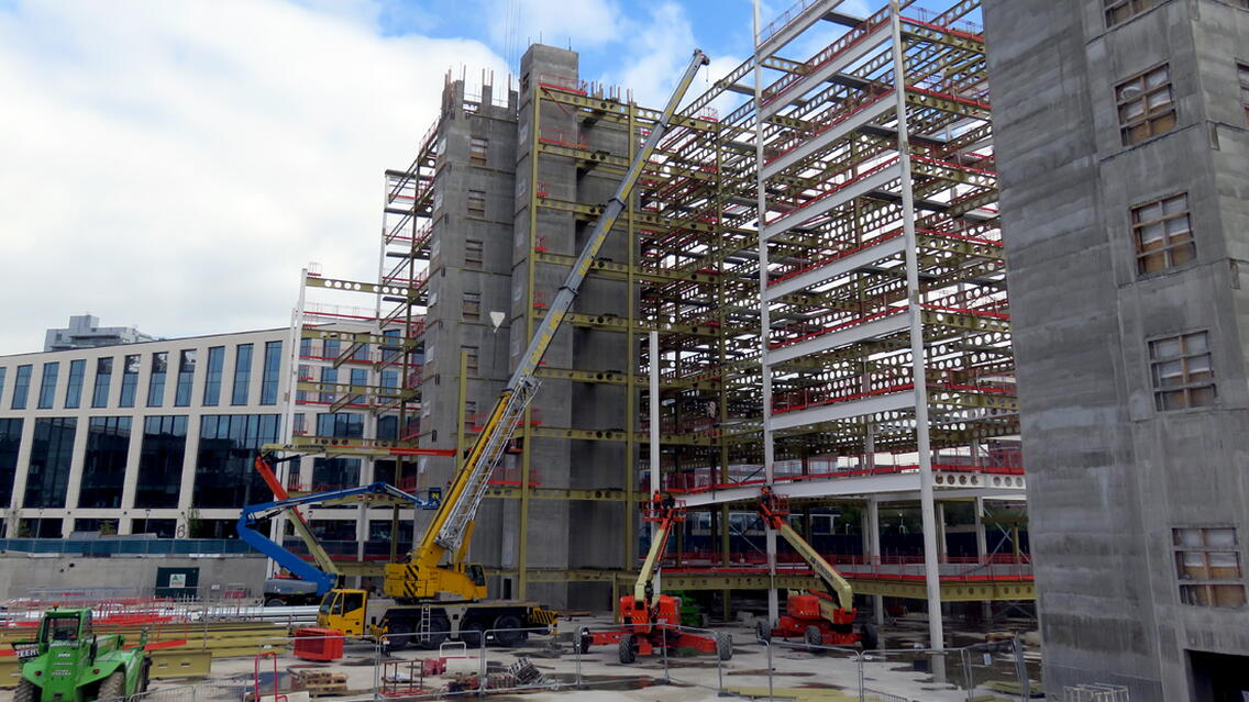
Billington Structures have provided over 4,100 tonnes of steel in total, across 5 individual structures varying from 6 to 9 storeys in height and 75,000 sq ft & 375,000 sq ft in area.
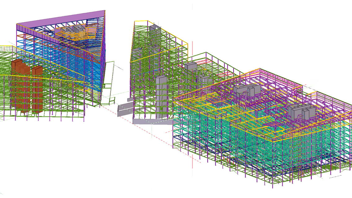
All five units have been detailed using Tekla Structures, with three units being designed in Tekla Structural Designer and models transferred directly between the software packages. The two other units were designed in Trimble (Fastrak) Building Designer.
What were the challenges and what made the project successful.
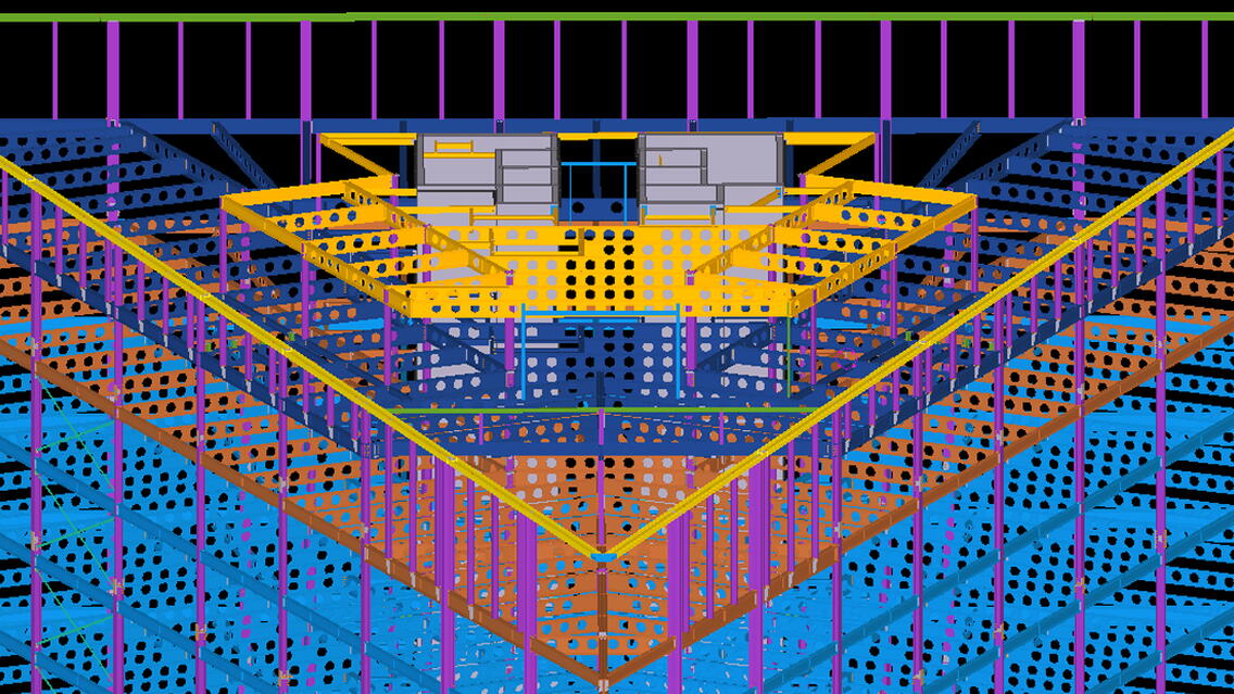
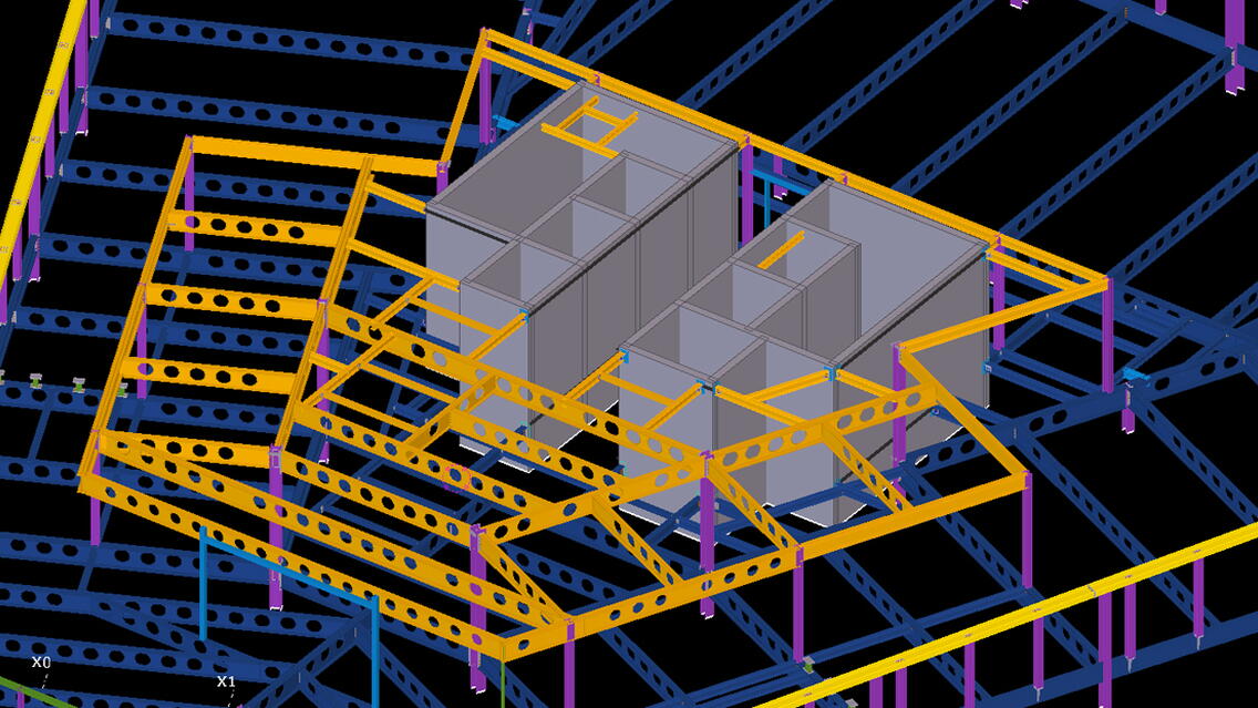
The most significant challenge was the shape of the buildings and how they sit together on the overall plan. The Masterplan was developed to resemble a cheeseboard, so that the buildings were a variety of shapes including parallelograms and a mixture of triangles.
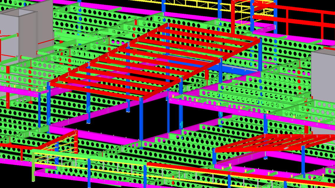
Another challenging aspect was the integration of the mechanical and electrical services within the structural zone to minimise both storey and overall building heights, but still maintain future client flexibility and large open plan floor spaces. This required the provision of large web openings within all primary and secondary beams and the detailed co-ordination of hole positions - a task assisted greatly through the use of Tekla Structural Designer and Tekla Structures.
What benefits utilizing BIM and Tekla Software brought to the project.
The projects have been very successful, which is demonstrated through the repeat involvement on successive units. A key success has been the use of a mixture of beam construction types, including Westok cellular, plate girders and rolled beams, to develop a highly efficient and therefore cost-effective structural design. By tailoring beam structural properties to the specific requirements for its position and loading, such as stocky rolled beams or fabricated beams with thick webs in members subject to concentrated loads or high vertical shear forces, it was possible to avoid excessive infilling or costly stiffening of web openings. Similarly, by tailoring beams structural properties to the minimum required where possible, such as for long-span composite secondary beams with asymmetric profiles, it permitted the minimum use of steel material and therefore reduced costs. The capabilities of Tekla Structural Designer have been invaluable in the development of the scheme designs.
Standardisation of connection details was utilised to maximise efficiency of detailing, fabrication and site-formed steel to concrete details. Some steel-to steel connections were specified as cut from standard width products to reduce waste plate during the fabrication process. The capabilities of Tekla Structures, including the ability to create macros for common repetitive details, has been invaluable in achieving these highly efficient ‘design for manufacture’ structures.
For the last three phases of Wellington Place, the models have initially been created in Tekla Structural Designer for analysis and design purposes. The Tekla Structural Designer IFC model export function has been used extensively to share these early stage analytical models with the design team to inform the developing overall building design. Similarly, the import functions to display architectural floor plans as shadows has been used for development of the steel design model.
Once this initial phase of co-ordination is complete and the design is sufficiently developed, the models were then transferred to the more detailed Tekla Structures environment. The detailed architectural coordination is then carried out using the Tekla Structures model, which will then incorporate the detail at intersections and joints, so that the design team can appreciate and understand the finalised structure to be provided. The Tekla Structures model is positioned to the project coordinates and shared in IFC format for clash detection purposes and detailed co-ordination with following trades such as M&E services.
Both Tekla Structural Designer and Tekla Structures models are loaded onto laptops which are taken to meetings & workshops to provide a more efficient and detailed discussion. The material information from the Tekla Structures 3D model is exported to StruMIS. The material information from the Tekla Structures 3D model is exported to Go-Data for production ordering purposes and NC files are created and exported to production for machine requirements. The Tekla Structures model is used to visualise and report which steel lots have been completed, checked and issued for fabrication. The Tekla Structures model is not used for continued progress through the following stages.
The project in numbers
Tonnage - 4,105 approx.
